Toyota Yaris: Vehicle Stability Control System / Brake Pressure Sensor "A" Circuit Voltage Above Threshold (C054017)
DESCRIPTION
| DTC No. | Detection Item | DTC Detection Condition | Trouble Area | DTC Output from |
|---|---|---|---|---|
| C054017 | Brake Pressure Sensor "A" Circuit Voltage Above Threshold | When vehicle speed exceeds 3 km/h (2 mph) and stop light switch assembly is OFF, master cylinder pressure continuously exceeds 1.764 MPa (18.0 kgf/cm2, 255 psi) for 5 seconds or more. |
| Brake |
WIRING DIAGRAM
Refer to DTC C13807E.
Click here

CAUTION / NOTICE / HINT
NOTICE:
- Inspect the fuses for circuits related to this system before performing the following procedure.
-
After replacing the skid control ECU (brake actuator assembly), perform "Calibration".
Click here

PROCEDURE
| 1. | CLEAR DTC |
(a) Operate the GTS to clear the codes.
Chassis > Brake > Clear DTCs(b) Press the DTC clear button.
(c) Turn the ignition switch off.
|

| 2. | RECONFIRM DTC |
(a) Based on the Freeze Frame Data and interview with the customer, attempt to reproduce the conditions when the malfunction occurred.
(b) Operate the GTS to read the DTCs.
Chassis > Brake > Trouble Codes(c) Check if the same DTC is output.
| Result | Proceed to |
|---|---|
| Only C054017 is output | A |
| C054017 and P057113 are output | B |
| None of the above conditions are met | C |
| B |
 | GO TO DTC CHART (P057113) |
| C |
 | REPAIR CIRCUITS INDICATED BY OUTPUT DTCS |
|

| 3. | READ VALUE USING GTS (STOP LIGHT SW) |
(a) Operate the GTS to check the Data List.
Chassis > Brake > Data List| Tester Display | Measurement Item | Range | Normal Condition | Diagnostic Note |
|---|---|---|---|---|
| Stop Light SW | Stop light switch assembly (STP terminal input) | OFF / ON | OFF: Brake pedal released ON: Brake pedal depressed | HINT: The brake pedal state is determined using the voltage at terminal STP |
| Tester Display |
|---|
| Stop Light SW |
(b) Check that the stop light switch assembly condition observed on the GTS changes according to brake pedal operation.
OK:
The GTS displays OFF / ON according to brake pedal operation.
| NG |
 | GO TO STEP 7 |
|

| 4. | READ VALUE USING GTS (MASTER CYLINDER SENSOR 1) |
(a) Operate the GTS to check the Data List.
Chassis > Brake > Data List| Tester Display | Measurement Item | Range | Normal Condition | Diagnostic Note |
|---|---|---|---|---|
| Master Cylinder Sensor 1 | Master cylinder pressure sensor pressure (value detected by ECU) | Min.: -1.00 MPa Max.: 23.99 MPa | Brake pedal released: -1.00 to 0.00 MPa | Reading increases when brake pedal is depressed |
| Tester Display |
|---|
| Master Cylinder Sensor 1 |
(b) Start the engine.
(c) Check the value of Data List item Master Cylinder Sensor 1 when the brake pedal is released.
OK:
The value of Data List item Master Cylinder 1 is within standard range.
| NG |
 | REPLACE BRAKE ACTUATOR ASSEMBLY |
|

| 5. | CLEAR DTC |
(a) Operate the GTS to clear the codes.
Chassis > Brake > Clear DTCs(b) Press the DTC clear button.
(c) Turn the ignition switch off.
|

| 6. | RECONFIRM DTC |
(a) Start the engine.
(b) Drive the vehicle and perform a braking test (decelerate the vehicle by depressing the brake pedal).
(c) Operate the GTS to read the DTCs.
Chassis > Brake > Trouble Codes(d) Check if the same DTC is output.
| Result | Proceed to |
|---|---|
| C054017 is not output | A |
| C054017 is output | B |
| A |
 | USE SIMULATION METHOD TO CHECK |
| B |
 | REPLACE BRAKE ACTUATOR ASSEMBLY |
| 7. | CHECK STOP LIGHT SWITCH ASSEMBLY INSTALLATION |
(a) Turn the ignition switch off.
(b) Check the stop light switch assembly installation.
Click here

OK:
The stop light switch assembly installation are normal.
| NG |
 | INSTALL STOP LIGHT SWITCH ASSEMBLY CORRECTLY |
|

| 8. | INSPECT STOP LIGHT SWITCH ASSEMBLY |
Click here

OK:
The stop light switch assembly is normal.
| NG |
 | REPLACE STOP LIGHT SWITCH ASSEMBLY |
|

| 9. | CHECK HARNESS AND CONNECTOR (STP TERMINAL) |
| (a) Make sure that there is no looseness at the locking part and the connecting part of the connectors. OK: The connector is securely connected. |
|
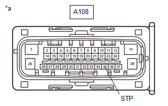
(b) Disconnect the A108 skid control ECU (brake actuator assembly) connector.
(c) Check both the connector case and the terminals for deformation and corrosion.
OK:
No deformation or corrosion.
(d) Measure the voltage according to the value(s) in the table below.
Standard Voltage:
| Tester Connection | Condition | Specified Condition |
|---|---|---|
| A108-35 (STP) - Body ground | Stop light switch assembly on (Brake pedal depressed) | 8 to 14 V |
| A108-35 (STP) - Body ground | Stop light switch assembly off (Brake pedal released) | Below 1.5 V |
| OK |
 | REPLACE BRAKE ACTUATOR ASSEMBLY |
| NG |
 | REPAIR OR REPLACE HARNESS OR CONNECTOR |
 ABS Pump Motor Control Circuit Voltage Out of Range (C052C1C)
DESCRIPTION DTC No. Detection Item DTC Detection Condition Trouble Area DTC Output from C052C1C ABS Pump Motor Control Circuit Voltage Out of Range Any of the following is detected:
When the +BS terminal voltage is from 9...
 Brake System Control Module "A" Internal Electronic Failure (C059749,...,C13C91C)
DESCRIPTION The solenoid relay and solenoid valves are built into the brake actuator assembly. The solenoid valves control the brake fluid pressure at each wheel cylinder...
Other information:
Toyota Yaris XP210 (2020-2025) Reapir and Service Manual: Registration
REGISTRATION PROCEDURE 1. REPAIR INSTRUCTION CAUTION: As weak radio waves are emitted from the electrical key transmitter sub-assembly, if a pacemaker is being used, be sure to read the pacemaker instruction manual and the following. People with implantable cardiac pacemakers, cardiac resynchronization therapy-pacemakers or implantable cardioverter defibrillators should keep away from the Smart Key system antennas...
Toyota Yaris XP210 (2020-2025) Reapir and Service Manual: Cruise SET Indicator Light Circuit
DESCRIPTION The ECM illuminates the cruise SET indicator by sending request signals to the combination meter assembly via CAN communication. The cruise SET indicator illuminates when the dynamic radar cruise control system is controlling vehicle speed...
Categories
- Manuals Home
- Toyota Yaris Owners Manual
- Toyota Yaris Service Manual
- To Set Speed
- Opening and Closing the Liftgate/Trunk Lid
- Fuse Panel Description
- New on site
- Most important about car
Supplemental Restraint System (SRS) Precautions
The front and side supplemental restraint systems (SRS) include different types of air bags. Please verify the different types of air bags which are equipped on your vehicle by locating the “SRS AIRBAG” location indicators. These indicators are visible in the area where the air bags are installed.
The air bags are installed in the following locations:
The steering wheel hub (driver air bag) The front passenger dashboard (front passenger air bag) The outboard sides of the front seatbacks (side air bags) The front and rear window pillars, and the roof edge along both sides (curtain air bags)