Toyota Yaris: Vehicle Stability Control System / ABS Pump Motor Control Circuit Open (C052C13,C052C49,C052F14)
DESCRIPTION
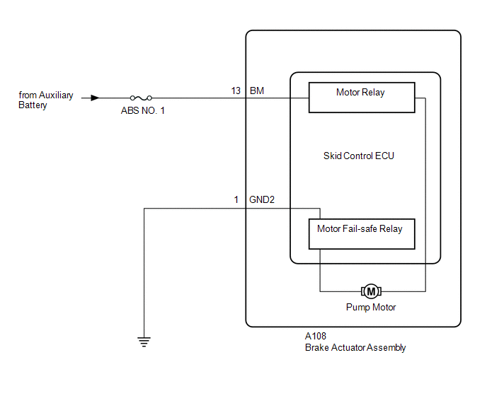
The motor relay and motor fail safe relay are built into the brake actuator assembly.
When the skid control ECU (brake actuator assembly) operate ABS, TRC, VSC or brake assist, the motor relay turns ON and drives the motor pump built into the brake actuator assembly.
If any DTCs related to motor supply power are stored, fail-safe is performed and supply of power to the motor relay is cut by the motor fail safe relay.
If the voltage supplied to the motor relay (BM) is below the DTC detection threshold due to low voltage from the auxiliary battery or alternator, these DTCs may be stored.
| DTC No. | Detection Item | DTC Detection Condition | Trouble Area | DTC Output from |
|---|---|---|---|---|
| C052C13 | ABS Pump Motor Control Circuit Open | Either of the following is detected:
|
| Brake |
| C052C49 | ABS Pump Motor Control Internal Electronic Failure | Any of the following is detected:
|
| Brake |
| C052F14 | ABS Pump Motor Supply Voltage Circuit Short to Ground or Open | When voltage at +BS terminal is 9.5 V or higher, open in BM terminal continues for 1 second or more. |
| Brake |
WIRING DIAGRAM
CAUTION / NOTICE / HINT
NOTICE:
- Inspect the fuses for circuits related to this system before performing the following procedure.
-
After replacing the skid control ECU (brake actuator assembly), perform "Calibration".
Click here

PROCEDURE
| 1. | CHECK HARNESS AND CONNECTOR (BM TERMINAL) |
| (a) Make sure that there is no looseness at the locking part and the connecting part of the connectors. OK: The connector is securely connected. |
|
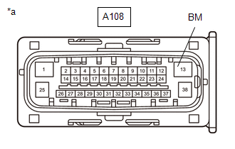
(b) Disconnect the A108 skid control ECU (brake actuator assembly) connector.
(c) Check both the connector case and the terminals for deformation and corrosion.
OK:
No deformation or corrosion.
(d) Measure the voltage according to the value(s) in the table below.
Standard Voltage:
| Tester Connection | Condition | Specified Condition |
|---|---|---|
| A108-13 (BM) - Body ground | Always | 11 to 14 V |
| NG |
 | REPAIR OR REPLACE HARNESS OR CONNECTOR |
|

| 2. | CHECK HARNESS AND CONNECTOR (GND2 TERMINAL) |
(a) Measure the resistance according to the value(s) in the table below.
Standard Resistance:
| Tester Connection | Condition | Specified Condition |
|---|---|---|
| A108-1 (GND2) - Body ground | 1 minute or more after disconnecting the cable from the negative (-) auxiliary battery terminal | Below 1 Ω |
| NG |
 | REPAIR OR REPLACE HARNESS OR CONNECTOR |
|

| 3. | CLEAR DTC |
(a) Reconnect the A108 skid control ECU (brake actuator assembly) connector.
(b) Operate the GTS to clear the codes.
Chassis > Brake > Clear DTCs(c) Press the DTC clear button.
(d) Turn the ignition switch off.
|

| 4. | RECONFIRM DTC |
(a) Start the engine.
(b) Drive the vehicle at a speed of 20 km/h (12 mph).
(c) Operate the GTS to read the DTCs.
Chassis > Brake > Trouble Codes(d) Check if the same DTC is output.
HINT:
- If a speed signal of 20 km/h (12 mph) or more is sent to the skid control ECU (brake actuator assembly) with the ignition switch ON and the stop light switch assembly off, the ECU performs self-diagnosis of the motor and solenoid circuits.
- If the normal system code is output (no DTCs are output), slightly jiggle the connectors, wire harness, and fuses of the skid control ECU (brake actuator assembly).
- If any DTCs are output while jiggling a connector or wire harness of the skid control ECU (brake actuator assembly), inspect and repair the connector or wire harness.
- If no DTCs were output when reconfirming DTCs, checking for intermittent problems is necessary because it is suspected that the original DTCs were stored due to the poor connection of a connector terminal.
| Result | Proceed to |
|---|---|
| C052C13, C052C49 and C052F14 are not output | A |
| C052C13, C052C49 or C052F14 is output | B |
| A |
 | USE SIMULATION METHOD TO CHECK |
| B |
 | REPLACE BRAKE ACTUATOR ASSEMBLY |
 Steering Angle Sensor Module Component Internal Failure (C052696)
DESCRIPTION The skid control ECU (brake actuator assembly) outputs this DTC when it receives an internal malfunction signal from the steering sensor. DTC No...
 ABS Pump Motor Control Circuit Voltage Out of Range (C052C1C)
DESCRIPTION DTC No. Detection Item DTC Detection Condition Trouble Area DTC Output from C052C1C ABS Pump Motor Control Circuit Voltage Out of Range Any of the following is detected:
When the +BS terminal voltage is from 9...
Other information:
Toyota Yaris XP210 (2020-2026) Reapir and Service Manual: Inspection
INSPECTION PROCEDURE 1. INSPECT AIR CONDITIONING CONTROL ASSEMBLY (a) Check the illumination. (1) Apply auxiliary battery voltage to the air conditioning control assembly and check that the illumination. OK: Measurement Condition Specified Condition Auxiliary battery positive (+) → H31-8 (ILL+) Auxiliary battery negative (-) → H31-14 (ILL-) Illumination illuminates If the result is not as specified, replace the air conditioning control assembly...
Toyota Yaris XP210 (2020-2026) Reapir and Service Manual: Installation
INSTALLATION CAUTION / NOTICE / HINT HINT: Use the same procedure for the RH side and LH side. The following procedure is for the LH side. PROCEDURE 1. INSTALL FRONT LOWER COIL SPRING INSULATOR (a) Install the front lower coil spring insulator to the front shock absorber assembly...
Categories
- Manuals Home
- Toyota Yaris Owners Manual
- Toyota Yaris Service Manual
- How to connect USB port/Auxiliary jack
- How to use USB mode
- Key Battery Replacement
- New on site
- Most important about car
Fuel Gauge
The fuel gauge shows approximately how much fuel is remaining in the tank when the ignition is switched ON. We recommend keeping the tank over 1/4 full.
