Toyota Yaris: Airbag System / Freeze Frame Data
FREEZE FRAME DATA
DESCRIPTION
(a) When an airbag system DTC is stored, the airbag sensor assembly stores the current vehicle (ECU, sensor or squib) state as Freeze Frame Data.
CHECK FREEZE FRAME DATA
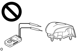
CAUTION:
Never measure the resistance of the SRS parts because current from the tester may cause the SRS parts to deploy.
(a) Check for DTCs.
Body Electrical > SRS Airbag > Trouble Codes(b) According to the GTS display, select a DTC that stored freeze frame data.
(c) Read the freeze frame data recorded when the DTC was stored.
Body Electrical > SRS Airbag| Tester Display | Measurement Item | Range | Normal Condition | Diagnostic Note |
|---|---|---|---|---|
| Total Distance Traveled | - | - | - | Not applicable |
| Total Distance Traveled - Unit | - | - | - | Not applicable |
| IG Voltage | IG power supply voltage supplied to airbag sensor assembly | 0 to 25.5 V | 12 V | - |
| Voltage After Pressure Rising | Airbag sensor assembly internal voltage | 0 to 51 V | 23.5 V | - |
| Squib Driver Voltage | Airbag sensor assembly internal voltage | 0 to 51 V | 23.5 V | - |
| Satellite Sensor Power Supply Voltage | Airbag sensor assembly internal voltage | 0 to 25.5 V | 9.4 V | - |
| Microcomputer/Sensor Voltage | Airbag sensor assembly internal voltage | 0 to 12.75 V | 3.3 V | - |
| Passenger Seat Manual Cut-off Switch Terminal Voltage (Live) | Voltage applied to airbag cut off switch cylinder sub-assembly (when energized) | 0 to 12.75 V | 5 V: Cut off switch in ON position 1.25 V: Cut off switch in OFF position | - |
| Passenger Seat Manual Cut-off Switch Terminal Voltage (Inactive) | Voltage applied to airbag cut off switch cylinder sub-assembly (when not energized) | 0 to 12.75 V | 0 V | - |
| Satellite G Sensor Output Value | Satellite G sensor output value | -100.000 to 99.804 % | 0 % | - |
| Satellite P Sensor Output Value | Satellite pressure sensor output value | 0 to 33.759 % | 0 % | - |
| Satellite P Sensor Absolute Pressure 1 | Absolute pressure output of satellite pressure sensor at initial diagnosis | 35.9223 to 147.5607 kPa(abs) | - | - |
| Satellite P Sensor Absolute Pressure 2 | Absolute pressure output of satellite pressure sensor at initial diagnosis | 35.9223 to 147.5607 kPa(abs) | - | - |
| Driver Seat Airbag Squib Resistance Value | Squib resistance value | 0 to 655.35 OHM | 2.10 to 4.20 OHM | - |
| Driver Seat Airbag Squib Resistance Value Diagnosis Result | Diagnostic result of squib resistance value | Normal or Abnormal | Normal | - |
| Passenger Seat Airbag Squib Resistance Value | Squib resistance value | 0 to 655.35 OHM | 1.80 to 3.00 OHM | - |
| Passenger Seat Airbag Squib Resistance Value Diagnosis Result | Diagnostic result of squib resistance value | Normal or Abnormal | Normal | - |
| Right Side 1st Seat Side-airbag Squib Resistance Value | Squib resistance value | 0 to 655.35 OHM | 1.80 to 3.00 OHM | - |
| Right Side 1st Seat Side-airbag Squib Resistance Value Diagnosis Result | Diagnostic result of squib resistance value | Normal or Abnormal | Normal | - |
| Left Side 1st Seat Side-airbag Squib Resistance Value | Squib resistance value | 0 to 655.35 OHM | 1.80 to 3.00 OHM | - |
| Left Side 1st Seat Side-airbag Squib Resistance Value Diagnosis Result | Diagnostic result of squib resistance value | Normal or Abnormal | Normal | - |
| Driver Seat Pretensioner Squib Resistance Value | Squib resistance value | 0 to 655.35 OHM | 1.80 to 3.00 OHM | - |
| Driver Seat Pretensioner Squib Resistance Value Diagnosis Result | Diagnostic result of squib resistance value | Normal or Abnormal | Normal | - |
| Passenger Seat Pretensioner Squib Resistance Value | Squib resistance value | 0 to 655.35 OHM | 1.80 to 3.00 OHM | - |
| Passenger Seat Pretensioner Squib Resistance Value Diagnosis Result | Diagnostic result of squib resistance value | Normal or Abnormal | Normal | - |
| Right Side 1st Seat Far Side Squib Resistance (Right Side 1st Seat Center Airbag) | Squib resistance value | 0 to 655.35 OHM | 1.80 to 3.00 OHM | Not applicable |
| Right Side 1st Seat Far Side Squib Resistance Diagnosis Result (Right Side 1st Seat Center Airbag) | Diagnostic result of squib resistance value | Normal or Abnormal | Normal | Not applicable |
| Left Side 1st Seat Far Side Squib Resistance (Left Side 1st Seat Center Airbag) | Squib resistance value | 0 to 655.35 OHM | 1.80 to 3.00 OHM | Not applicable |
| Left Side 1st Seat Far Side Squib Resistance Diagnosis Result (Left Side 1st Seat Center Airbag) | Diagnostic result of squib resistance value | Normal or Abnormal | Normal | Not applicable |
| Right Side Curtain Shield Airbag Squib Resistance Value | Squib resistance value | 0 to 655.35 OHM | 1.80 to 3.00 OHM | - |
| Right Side Curtain Shield Airbag Squib Resistance Value Diagnosis Result | Diagnostic result of squib resistance value | Normal or Abnormal | Normal | - |
| Left Side Curtain Shield Airbag Squib Resistance Value | Squib resistance value | 0 to 655.35 OHM | 1.80 to 3.00 OHM | - |
| Left Side Curtain Shield Airbag Squib Resistance Value Diagnosis Result | Diagnostic result of squib resistance value | Normal or Abnormal | Normal | - |
| Right Side 2nd Seat Pretensioner Squib Resistance Value | Squib resistance value | 0 to 655.35 OHM | 1.80 to 3.00 OHM | Not applicable |
| Right Side 2nd Seat Pretensioner Squib Resistance Value Diagnosis Result | Diagnostic result of squib resistance value | Normal or Abnormal | Normal | Not applicable |
| Left Side 2nd Seat Pretensioner Squib Resistance Value | Squib resistance value | 0 to 655.35 OHM | 1.80 to 3.00 OHM | Not applicable |
| Left Side 2nd Seat Pretensioner Squib Resistance Value Diagnosis Result | Diagnostic result of squib resistance value | Normal or Abnormal | Normal | Not applicable |
 Dtc Check / Clear
DTC CHECK / CLEAR DTC CHECK (a) Turn the ignition switch to ON, and wait for at least 60 seconds. (b) Check for DTCs by following the prompts on the GTS screen...
 Check Mode Procedure
CHECK MODE PROCEDURE CHECK MODE: DTC CHECK (a) Select "Check Mode" and proceed with checking using the GTS. Body Electrical > SRS Airbag > Utility Tester Display Check Mode NOTICE: Select Check Mode on the GTS to clear the DTCs (both current and history)...
Other information:
Toyota Yaris XP210 (2020-2026) Owner's Manual: Jam-safe window
If foreign matter is detected between the window and the window frame while the window is closing automatically, the window stops closing and automatically opens partway. Jam-safe window The jam-safe function may operate under the following conditions A strong impact is detected while the window is closing automatically...
Toyota Yaris XP210 (2020-2026) Reapir and Service Manual: Components
C..
Categories
- Manuals Home
- Toyota Yaris Owners Manual
- Toyota Yaris Service Manual
- How to connect USB port/Auxiliary jack
- Fuel Gauge
- Headlights
- New on site
- Most important about car
Break-In Period
No special break-in is necessary, but a few precautions in the first 600 miles (1,000 km) may add to the performance, economy, and life of the vehicle.
Do not race the engine. Do not maintain one constant speed, either slow or fast, for a long period of time. Do not drive constantly at full-throttle or high engine rpm for extended periods of time. Avoid unnecessary hard stops. Avoid full-throttle starts.