Toyota Yaris: Sfi System / Starter Signal Circuit
DESCRIPTION
While the engine is being cranked, current flows from terminal STAR of the certification ECU (smart key ECU assembly) to the clutch start switch assembly and to terminal STA of the ECM (STA signal).
WIRING DIAGRAM
Refer to DTC P061512.
Click here

CAUTION / NOTICE / HINT
NOTICE:
Inspect the fuses for circuits related to this system before performing the following procedure.
- Inspect the fuses for circuits related to this system before performing the following procedure.
-
After turning ignition switch off, waiting time may be required before disconnecting the cable from the negative (-) auxiliary battery terminal. Therefore, make sure to read the disconnecting the cable from the negative (-) auxiliary battery terminal notices before proceeding with work.
Click here

-
When the starter assembly is replaced, the number of starter operations stored in the engine stop and start ECU must be reset.
Click here

- When the starter assembly is replaced, "ST NO. 1 relay" must be also replaced.
PROCEDURE
| 1. | CHECK WHETHER ENGINE CAN BE CRANKED |
(a) Check if the engine can be cranked.
| Result | Proceed to |
|---|---|
| Engine cannot be cranked | A |
| Engine can be cranked | B |
| B |
 | GO TO STEP 14 |
|

| 2. | READ VALUE USING GTS (STARTER SW) |
(a) Fully depress the clutch pedal.
(b) Check the value displayed on the GTS when the ignition switch is turned to ON and START positions.
Powertrain > Engine > Data List| Tester Display |
|---|
| Starter SW |
OK:
| Condition | GTS Display (Starter SW) |
|---|---|
| Ignition switch ON | OFF |
| Engine started | ON |
| OK |
 | GO TO STEP 7 |
|

| 3. | CHECK STOP AND START SYSTEM |
(a) Check the stop and start system.
Click here

| NG |
 | REPAIR STOP AND START SYSTEM |
|

| 4. | INSPECT CLUTCH START SWITCH ASSEMBLY |
Click here

| NG |
 | REPLACE CLUTCH START SWITCH ASSEMBLY |
|

| 5. | CHECK HARNESS AND CONNECTOR (STA SIGNAL CIRCUIT) |
(a) Disconnect the engine stop and start ECU connector.
(b) Disconnect the ECM connector.
(c) Remove the ST NO. 1 relay from No. 1 engine room relay block assembly.
(d) Disconnect the clutch start switch assembly connector.
(e) Disconnect the certification ECU (smart key ECU assembly) connector.
(f) Measure the resistance according to the value(s) in the table below.
Standard Resistance:
| Tester Connection | Condition | Specified Condition |
|---|---|---|
| A64-1 (L) - 2 (ST NO. 1 relay) | Always | Below 1 Ω |
| A106-30 (STA) - 2 (ST NO. 1 relay) | Always | Below 1 Ω |
| A67-21 (STA) - 2 (ST NO. 1 relay) | Always | Below 1 Ω |
| H45-3 (STA) - 2 (ST NO. 1 relay) | Always | Below 1 Ω |
| H45-3 (STA), 2 (ST NO. 1 relay), A64-1 (L) or A106-30 (STA) - Body ground and other terminals | Always | 10 kΩ or higher |
| NG |
 | REPAIR OR REPLACE HARNESS OR CONNECTOR |
|

| 6. | CHECK HARNESS AND CONNECTOR (CERTIFICATION ECU - CLUTCH START SWITCH ASSEMBLY - ECM - ENGINE STOP AND START ECU) |
(a) Disconnect the certification ECU (smart key ECU assembly) connector.
(b) Disconnect the clutch start switch assembly connector.
(c) Disconnect the ECM connector.
(d) Disconnect the engine stop and start ECU connector.
(e) Measure the resistance according to the value(s) in the table below.
Standard Resistance:
| Tester Connection | Condition | Specified Condition |
|---|---|---|
| H45-10 (STAR) - A64-2 (B) | Always | Below 1 Ω |
| H45-10 (STAR) - A67-17 (CLL) | Always | Below 1 Ω |
| A67-17 (CLL) - A106-23 (NSW) | Always | Below 1 Ω |
| H45-10 (STAR), A67-17 (CLL), A106-23 (NSW) or A64-2 (B) - Body ground and other terminals | Always | 10 kΩ or higher |
| OK |
 | GO TO ENTRY AND START SYSTEM |
| NG |
 | REPAIR OR REPLACE HARNESS OR CONNECTOR |
| 7. | INSPECT ST NO. 1 RELAY |
Click here

| NG |
 | REPLACE ST NO. 1 RELAY |
|

| 8. | INSPECT STARTER ASSEMBLY |
Click here

| NG |
 | REPLACE STARTER ASSEMBLY |
|

| 9. | CHECK HARNESS AND CONNECTOR (ST NO. 1 RELAY - STARTER ASSEMBLY) |
(a) Remove the ST NO. 1 relay from No. 1 engine room relay block assembly.
(b) Disconnect the starter assembly connector.
(c) Measure the resistance according to the value(s) in the table below.
Standard Resistance:
| Tester Connection | Condition | Specified Condition |
|---|---|---|
| 3 (ST NO. 1 relay) - D54-1 (ST) | Always | Below 1 Ω |
| 3 (ST NO. 1 relay) or D54-1 (ST) - Body ground and other terminals | Always | 10 kΩ or higher |
| NG |
 | REPAIR OR REPLACE HARNESS OR CONNECTOR |
|

| 10. | CHECK TERMINAL VOLTAGE (AUXILIARY BATTERY - STARTER ASSEMBLY) |
(a) Disconnect the cable from the negative (-) auxiliary battery terminal.
(b) Disconnect the cable from the positive (+) auxiliary battery terminal.
(c) Disconnect the starter assembly connector.
(d) Measure the resistance according to the value(s) in the table below.
Standard Resistance:
| Tester Connection | Condition | Specified Condition |
|---|---|---|
| Positive (+) auxiliary battery terminal - D80-1 (B) | Always | Below 1 Ω |
| NG |
 | REPAIR OR REPLACE HARNESS OR CONNECTOR |
|

| 11. | CHECK TERMINAL VOLTAGE (POWER SOURCE OF ST NO. 1 RELAY) |
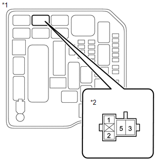
| *1 | No. 1 Engine Room Relay Block Assembly |
| *2 | ST NO. 1 Relay |
(a) Remove the ST NO. 1 relay from No. 1 engine room relay block assembly.
(b) Measure the voltage according to the value(s) in the table below.
Standard Voltage:
| Tester Connection | Condition | Specified Condition |
|---|---|---|
| 5 (ST NO. 1 relay) - Body ground | Always | 11 to 14 V |
| NG |
 | REPAIR OR REPLACE HARNESS OR CONNECTOR (AUXILIARY BATTERY - ST NO 1 RELAY) |
|

| 12. | CHECK HARNESS AND CONNECTOR (ST NO. 1 RELAY - BODY GROUND) |
(a) Remove the ST NO. 1 relay from No. 1 engine room relay block assembly.
(b) Measure the resistance according to the value(s) in the table below.
Standard Resistance:
| Tester Connection | Condition | Specified Condition |
|---|---|---|
| 1 (ST NO. 1 relay) - Body ground | Always | Below 1 Ω |
| NG |
 | REPAIR OR REPLACE HARNESS OR CONNECTOR |
|

| 13. | CHECK HARNESS AND CONNECTOR (ST NO. 1 RELAY - CLUTCH START SWITCH ASSEMBLY) |
(a) Remove the ST NO. 1 relay from the No. 1 engine room relay block assembly.
(b) Disconnect the clutch start switch assembly connector.
(c) Measure the resistance according to the value(s) in the table below.
Standard Resistance:
| Tester Connection | Condition | Specified Condition |
|---|---|---|
| 2 (ST NO. 1 relay) - A64-1 (L) | Always | Below 1 Ω |
| OK |
 | REPAIR OR REPLACE HARNESS OR CONNECTOR (AUXILIARY BATTERY - STARTER ASSEMBLY) |
| NG |
 | REPAIR OR REPLACE HARNESS OR CONNECTOR |
| 14. | READ VALUE USING GTS (STARTER SW) |
(a) Fully depress the clutch pedal.
(b) Check the value displayed on the GTS when the ignition switch is turned to ON and START positions.
Powertrain > Engine > Data List| Tester Display |
|---|
| Starter SW |
OK:
| Condition | GTS Display (Starter SW) |
|---|---|
| Ignition switch ON | OFF |
| Engine started | ON |
| Result | Proceed to |
|---|---|
| OK | A |
| NG | B |
| A |
 | PROCEED TO NEXT SUSPECTED AREA SHOWN IN PROBLEM SYMPTOMS TABLE |
| B |
 | REPAIR OR REPLACE HARNESS OR CONNECTOR (ST NO. 1 RELAY - ECM) |
 Fuel Pump Control Circuit
DESCRIPTION The fuel pump circuit consists of the ECM, fuel pump and fuel pump control ECU (which operates the fuel pump). Based on the engine output, the ECM determines the fuel pump speed...
 Brake Override System
DESCRIPTION When the vehicle is being driven, depressing the accelerator pedal sensor assembly and brake pedal will activate the brake override system to restrict engine output...
Other information:
Toyota Yaris XP210 (2020-2026) Reapir and Service Manual: Internal Control Module Software Incompatibility Not Programmed (U030051,U030057)
DESCRIPTION The forward recognition camera receives vehicle information from the ECM via CAN communication. DTC U030051 is stored when the vehicle information from the ECM cannot be confirmed. The forward recognition camera receives the vehicle information from the ECM via CAN communication...
Toyota Yaris XP210 (2020-2026) Reapir and Service Manual: Components
C..
Categories
- Manuals Home
- Toyota Yaris Owners Manual
- Toyota Yaris Service Manual
- G16e-gts (engine Mechanical)
- Engine Start Function When Key Battery is Dead
- Fuse Panel Description
- New on site
- Most important about car
Supplemental Restraint System (SRS) Precautions
The front and side supplemental restraint systems (SRS) include different types of air bags. Please verify the different types of air bags which are equipped on your vehicle by locating the “SRS AIRBAG” location indicators. These indicators are visible in the area where the air bags are installed.
The air bags are installed in the following locations:
The steering wheel hub (driver air bag) The front passenger dashboard (front passenger air bag) The outboard sides of the front seatbacks (side air bags) The front and rear window pillars, and the roof edge along both sides (curtain air bags)