Toyota Yaris: Sfi System / Fuel Pump Control Circuit
DESCRIPTION
The fuel pump circuit consists of the ECM, fuel pump and fuel pump control ECU (which operates the fuel pump). Based on the engine output, the ECM determines the fuel pump speed. The speed is then converted to a duty signal and sent to the fuel pump control ECU. Based on the signal sent from the ECM, the fuel pump control ECU adjusts the fuel pump operation speed.
WIRING DIAGRAM
Refer to DTC P062712.
Click here

CAUTION / NOTICE / HINT
NOTICE:
Inspect the fuses for circuits related to this system before performing the following procedure.
PROCEDURE
| 1. | CHECK FUEL LEAK |
(a) Check around and beneath the vehicle for fuel leaks, fumes, etc.
OK:
No fuel leaks present.
| NG |
 | REPAIR OR REPLACE FUEL LEAK POINT |
|

| 2. | PERFORM ACTIVE TEST USING GTS (ACTIVATE THE CIRCUIT RELAY (BRUSHLESS)) |
(a) Check whether the fuel pump operating sound occurs when performing the Active Test on the GTS.
Powertrain > Engine > Active Test| Tester Display |
|---|
| Activate the Circuit Relay (Brushless) |
Standard:
| GTS Operation | Standard |
|---|---|
| ON | Operating sounds can be heard from fuel pump (for low pressure side) |
| NG |
 | GO TO STEP 7 |
|

| 3. | PERFORM ACTIVE TEST USING GTS (CONTROL THE FUEL PUMP DUTY RATIO (BRUSHLESS)) |
(a) Install the fuel pressure gauge (for low pressure line of low pressure side).
Click here

(b) Compare the values in the Data List using the GTS and the fuel pressure gauge when the Active Test was performed.
Powertrain > Engine > Active Test| Active Test Display |
|---|
| Control the Fuel Pump Duty Ratio (Brushless) |
| Data List Display |
|---|
| Target Fuel Pressure (Low) / Target Fuel Pressure 2 |
| Fuel Pump Control Duty Ratio |
Standard:
| GTS Operation | Standard |
|---|---|
| Low | Data List value and fuel pressure gauge are within +/-50 kPa of each other |
| High |
| NG |
 | REPLACE FUEL PRESSURE SENSOR (FOR LOW PRESSURE SIDE) |
|

| 4. | READ VALUE USING GTS (FUEL PRESSURE) |
(a) Read the values displayed on the GTS while the engine is cranking.
Powertrain > Engine > Data List| Tester Display |
|---|
| Target Fuel Pressure (Low) / Target Fuel Pressure 2 |
| Fuel Pressure (Low) / Fuel Pressure 2 |
| Low Fuel Pressure Sensor |
| Result | Proceed to |
|---|---|
| Low Fuel Pressure Sensor value is within +/- 65 kPa of the Target Fuel Pressure (Low) / Target Fuel Pressure 2 | A |
| Low Fuel Pressure Sensor value is higher than 65 kPa higher than the target fuel pressure (low) | B |
| Low Fuel Pressure Sensor value is higher than 65 kPa lower than the target fuel pressure (low) | C |
| B |
 | REPLACE FUEL PUMP (FOR LOW PRESSURE SIDE) |
| C |
 | GO TO STEP 6 |
|

| 5. | CHECK FUEL PRESSURE |
(a) Install the fuel pressure gauge (for low pressure line of low pressure side).
Click here

(b) Start the engine.
(c) Measure the fuel pressure at idle.
Standard Fuel Pressure:
196 to 833 kPa (2.0 to 8.5 kgf/cm2, 28 to 121 psi)
HINT:
Refer to Standard Idle Speed.
Click here

(d) Stop the engine.
(e) Check that the fuel pressure remains as specified for 5 minutes.
Standard Fuel Pressure:
98 kPa (1.0 kgf/cm2, 14.2 psi) or higher
| OK |
 | PROCEED TO NEXT SUSPECTED AREA SHOWN IN PROBLEM SYMPTOMS TABLE |
| NG |
 | REPLACE FUEL PUMP (FOR LOW PRESSURE SIDE) |
| 6. | CHECK SHORTAGE OF FUEL |
(a) Check the amount of fuel remaining.
HINT:
- No fuel remains in the fuel tank: Malfunction of the fuel sender gauge assembly is suspected.
- Only the fuel pump side fuel chamber has no fuel remaining: Malfunction of the jet pump is suspected.
- Fuel remains in the fuel tank: Malfunction of the fuel pump (for low pressure side) is suspected.
| NEXT |
 | REPLACE FUEL PUMP (FOR LOW PRESSURE SIDE) |
| 7. | PERFORM ACTIVE TEST USING GTS (FUEL PUMP SINGLE PHASE ENERGIZATION) |
(a) Disconnect the fuel pump (for low pressure side) connector.
| (b) Operate the fuel pump control ECU using the Active Test function and measure the voltage according to the value(s) in the table below. Powertrain > Engine > Active Test
Standard Voltage:
HINT:
|
|
| OK |
 | REPLACE FUEL PUMP (FOR LOW PRESSURE SIDE) |
|

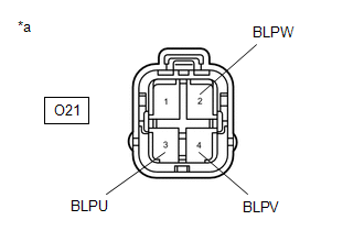
| 8. | CHECK HARNESS AND CONNECTOR (FUEL PUMP (FOR LOW PRESSURE SIDE) - FUEL PUMP CONTROL ECU) |
(a) Disconnect the fuel pump (for low pressure side) connector.
(b) Disconnect the fuel pump control ECU connector.
(c) Measure the resistance according to the value(s) in the table below.
Standard Resistance:
| Tester Connection | Condition | Specified Condition |
|---|---|---|
| O21-3 (BLPU) - O1-2 (FPU) | Always | Below 1 Ω |
| O21-4 (BLPV) - O1-3 (FPV) | Always | Below 1 Ω |
| O21-2 (BLPW) - O1-4 (FPW) | Always | Below 1 Ω |
| O21-3 (BLPU) or O1-2 (FPU) - Body ground and other terminals | Always | 10 kΩ or higher |
| O21-4 (BLPV) or O1-3 (FPV) - Body ground and other terminals | Always | 10 kΩ or higher |
| O21-2 (BLPW) or O1-4 (FPW) - Body ground and other terminals | Always | 10 kΩ or higher |
| NG |
 | REPAIR OR REPLACE HARNESS OR CONNECTOR |
|

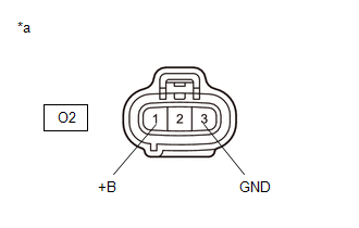
| 9. | CHECK HARNESS AND CONNECTOR (POWER SOURCE OF FUEL PUMP CONTROL ECU) |
(a) Disconnect the fuel pump control ECU connector.
(b) Turn the ignition switch to ON.
| (c) Measure the voltage according to the value(s) in the table below. Standard Voltage:
|
|
| NG |
 | GO TO STEP 12 |
|

| 10. | INSPECT ECM (FPC TERMINAL) |
(a) Disconnect the fuel pump control ECU connector.
(b) Operate the fuel pump control ECU using the Active Test function and measure the resistance according to the value(s) in the table below.
Powertrain > Engine > Active Test| Tester Display |
|---|
| Fuel Pump Single Phase Energization |
Standard Resistance:
| Tester Connection | GTS Operation | Specified Condition |
|---|---|---|
| O2-2 (FPC) - Body ground | Before Active Test → During Active Test | Before Active Test: Resistance is stable → During Active Test: Resistance fluctuates* |
HINT:
*: Using the Active Test, duty control of the transistors in the ECM will be performed. Due to the duty control, resistance of the FPC terminal will be unstable during the Active Test. If the resistance is stable before the Active Test and fluctuates while performing the Active Test, it can be determined that the transistor is operating. If the transistor does not operate during the Active Test, the ECM may be malfunctioning.
| OK |
 | REPLACE FUEL PUMP CONTROL ECU |
|

| 11. | CHECK HARNESS AND CONNECTOR (FUEL PUMP CONTROL ECU - ECM) |
(a) Disconnect the fuel pump control ECU connector.
(b) Disconnect the ECM connector.
(c) Measure the resistance according to the value(s) in the table below.
Standard Resistance:
| Tester Connection | Condition | Specified Condition |
|---|---|---|
| O2-2 (FPC) - A106-6 (FPC) | Always | Below 1 Ω |
| O2-2 (FPC) or A106-6 (FPC) - Body ground and other terminals | Always | 10 kΩ or higher |
| OK |
 | REPLACE ECM |
| NG |
 | REPAIR OR REPLACE HARNESS OR CONNECTOR |
| 12. | CHECK HARNESS AND CONNECTOR (FUEL PUMP CONTROL ECU - BODY GROUND) |
(a) Disconnect the fuel pump control ECU connector.
(b) Measure the resistance according to the value(s) in the table below.
Standard Resistance:
| Tester Connection | Condition | Specified Condition |
|---|---|---|
| O2-3 (GND) - Body ground | Always | Below 1 Ω |
| NG |
 | REPAIR OR REPLACE HARNESS OR CONNECTOR |
|

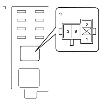
| 13. | CHECK HARNESS AND CONNECTOR (POWER SOURCE VOLTAGE OF EFI-MAIN NO. 2 RELAY) |
(a) Remove the EFI-MAIN NO. 2 relay from the No. 5 luggage room relay block assembly.
| (b) Measure the voltage according to the value(s) in the table below. Standard Voltage:
|
|
| NG |
 | REPAIR OR REPLACE HARNESS OR CONNECTOR (AUXILIARY BATTERY - EFI-MAIN NO. 2 RELAY) |
|

| 14. | INSPECT EFI-MAIN NO. 2 RELAY |
Click here

| NG |
 | REPLACE EFI-MAIN NO. 2 RELAY |
|

| 15. | CHECK HARNESS AND CONNECTOR (EFI-MAIN NO. 1 RELAY - EFI-MAIN NO. 2 RELAY) |
(a) Remove the EFI-MAIN NO. 2 relay from the No. 5 luggage room relay block assembly.
(b) Remove the EFI-MAIN NO. 1 relay, EFI-MAIN NO. 3 relay and EDU relay from the No. 1 engine room relay block assembly.
HINT:
Remove the VVT and EFI-MAIN NO. 3 relay and EDU relay connected between the checked terminals as the coil inside the relay influences the measurement value.
(c) Measure the resistance according to the value(s) in the table below.
Standard Resistance:
| Tester Connection | Condition | Specified Condition |
|---|---|---|
| 5 (EFI-MAIN NO. 1 relay holder) - 2 (EFI-MAIN NO. 2 relay holder) | Always | Below 1 Ω |
| 5 (EFI-MAIN NO. 1 relay holder) or 2 (EFI-MAIN NO. 2 relay holder) - Body ground and other terminals | Always | 10 kΩ or higher |
| NG |
 | REPAIR OR REPLACE HARNESS OR CONNECTOR |
|

| 16. | CHECK HARNESS AND CONNECTOR (EFI-MAIN NO. 2 RELAY - BODY GROUND) |
(a) Remove the EFI-MAIN NO. 2 relay from the No. 5 luggage room relay block assembly.
(b) Measure the resistance according to the value(s) in the table below.
Standard Resistance:
| Tester Connection | Condition | Specified Condition |
|---|---|---|
| 1 (EFI-MAIN NO. 2 relay holder) - Body ground | Always | Below 1 Ω |
| NG |
 | REPAIR OR REPLACE HARNESS OR CONNECTOR |
|

| 17. | CHECK HARNESS AND CONNECTOR (EFI-MAIN NO. 2 RELAY - FUEL PUMP CONTROL ECU) |
(a) Remove the EFI-MAIN NO. 2 relay from the No. 5 luggage room relay block assembly.
(b) Disconnect the fuel pump control ECU connector.
(c) Measure the resistance according to the value(s) in the table below.
Standard Resistance:
| Tester Connection | Condition | Specified Condition |
|---|---|---|
| 5 (EFI-MAIN NO. 2 relay holder) - O2-1 (+B) | Always | Below 1 Ω |
| 5 (EFI-MAIN NO. 2 relay holder) or O2-1 (+B) - Body ground and other terminals | Always | 10 kΩ or higher |
| OK |
 | GO TO ECM POWER SOURCE CIRCUIT |
| NG |
 | REPAIR OR REPLACE HARNESS OR CONNECTOR |
 VC Output Circuit
DESCRIPTION The ECM constantly generates a 5 V power source voltage from the auxiliary battery voltage supplied to the +B, +B2 (BATT) terminals to operate the microprocessor...
 Starter Signal Circuit
DESCRIPTION While the engine is being cranked, current flows from terminal STAR of the certification ECU (smart key ECU assembly) to the clutch start switch assembly and to terminal STA of the ECM (STA signal)...
Other information:
Toyota Yaris XP210 (2020-2026) Reapir and Service Manual: Speed Signal Circuit
DESCRIPTION HINT: This circuit is used for the systems connected to terminal +S. This signal is not used for combination meter assembly operation. Combination meter assembly components such as the speedometer operate using data received via CAN communication...
Toyota Yaris XP210 (2020-2026) Reapir and Service Manual: Diagnostic Trouble Code Chart
D..
Categories
- Manuals Home
- Toyota Yaris Owners Manual
- Toyota Yaris Service Manual
- Auto Lock/Unlock Function
- Fuel Gauge
- G16e-gts (engine Mechanical)
- New on site
- Most important about car
Break-In Period
No special break-in is necessary, but a few precautions in the first 600 miles (1,000 km) may add to the performance, economy, and life of the vehicle.
Do not race the engine. Do not maintain one constant speed, either slow or fast, for a long period of time. Do not drive constantly at full-throttle or high engine rpm for extended periods of time. Avoid unnecessary hard stops. Avoid full-throttle starts.