Toyota Yaris: Sfi System / VC Output Circuit
DESCRIPTION
The ECM constantly generates a 5 V power source voltage from the auxiliary battery voltage supplied to the +B, +B2 (BATT) terminals to operate the microprocessor. The ECM also provides this power to the sensors through the VC output circuit.
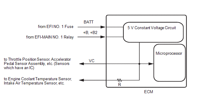
When the VC circuit has a short circuit, the microprocessor in the ECM and sensors that are supplied power through the VC circuit are deactivated because power is not supplied from the VC circuit. When the system is in this condition, it will not start.
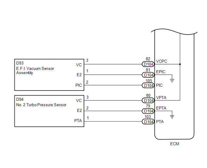
WIRING DIAGRAM
-
For the circuit diagram of the ECM power source refer to the ECM power source circuit.
Click here

-
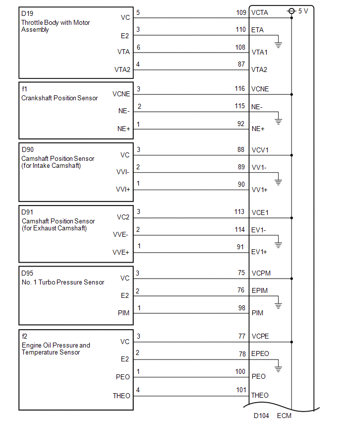
VC Output Circuit Production date from 2021/04 to 2021/07
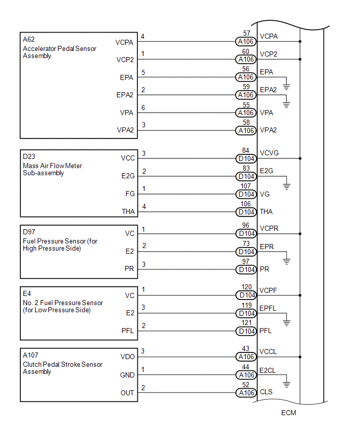
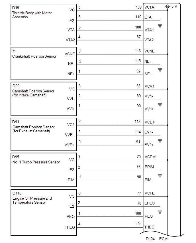
 Production date from 2021/07

CAUTION / NOTICE / HINT
NOTICE:
Check the fuses for circuits related to this system before performing the following inspection procedure.
PROCEDURE
| 1. | CHECK VEHICLE SPECIFICATION |
(a) Check the vehicle specification
| Result | Proceed to |
|---|---|
| Production date from 2021/04 to 2021/07 | A |
| Production date from 2021/07 | B |
| B |
 | GO TO STEP 18 |
|

| 2. | CHECK CONNECTION BETWEEN GTS AND ECM |
(a) Check the communication between the GTS and ECM.
HINT:
It can be checked using the "Engine" item of the Data List.
| Result | Proceed to |
|---|---|
| Communication is not possible | A |
| Communication is possible | B |
| B |
 | PROCEED TO NEXT SUSPECTED AREA SHOWN IN PROBLEM SYMPTOMS TABLE |
|

| 3. | CHECK EFI NO. 1 FUSE VOLTAGE |
(a) Turn the ignition switch to ON.
(b) Measure the voltage according to the value(s) in the table below.
Standard Voltage:
| Tester Connection | Condition | Specified Condition |
|---|---|---|
| 1 (EFI NO. 1 fuse) - Body ground | Ignition switch ON | 11 to 14 V |
HINT:
- Check the fuse with it installed to the No. 1 engine room relay block assembly.
- If the result is not as specified, since current is not flowing to the +B terminals of the ECM, the system may not be started.
| NG |
 | GO TO ECM POWER SOURCE CIRCUIT |
|

| 4. | CHECK CONNECTION BETWEEN GTS AND ECM (THROTTLE POSITION SENSOR) |
(a) Disconnect the throttle body with motor assembly connector.
(b) Check the communication between the GTS and ECM.
HINT:
It can be checked using the "Engine" item of the Data List.
| Result | Proceed to |
|---|---|
| Communication is not possible | A |
| Communication is possible | B |
HINT:
-
When cleaning or replacing one throttle body with motor assembly, clean the other throttle body with motor assembly.
Click here

-
Perform "Inspection After Repair" after replacing the throttle body with motor assembly.
Click here

| B |
 | REPLACE THROTTLE BODY WITH MOTOR ASSEMBLY |
|

| 5. | CHECK COMMUNICATION BETWEEN GTS AND ECM (CRANKSHAFT POSITION SENSOR) |
(a) Disconnect the crankshaft position sensor connector.
(b) Check the communication between the GTS and ECM.
HINT:
It can be checked using the "Engine" item of the Data List.
| Result | Proceed to |
|---|---|
| Communication is not possible | A |
| Communication is possible | B |
| B |
 | REPLACE CRANK POSITION SENSOR |
|

| 6. | CHECK COMMUNICATION BETWEEN GTS AND ECM (CAMSHAFT POSITION SENSOR (FOR INTAKE CAMSHAFT)) |
(a) Disconnect the camshaft position sensor (for intake camshaft) connector.
(b) Check the communication between the GTS and ECM.
HINT:
It can be checked using the "Engine" item of the Data List.
| Result | Proceed to |
|---|---|
| Communication is not possible | A |
| Communication is possible | B |
| B |
 | REPLACE CAMSHAFT POSITION SENSOR (FOR INTAKE CAMSHAFT) |
|

| 7. | CHECK COMMUNICATION BETWEEN GTS AND ECM (CAMSHAFT POSITION SENSOR (FOR EXHAUST CAMSHAFT)) |
(a) Disconnect the camshaft position sensor (for exhaust camshaft) connector.
(b) Check the communication between the GTS and ECM.
HINT:
It can be checked using the "Engine" item of the Data List.
| Result | Proceed to |
|---|---|
| Communication is not possible | A |
| Communication is possible | B |
| B |
 | REPLACE CAMSHAFT POSITION SENSOR (FOR EXHAUST CAMSHAFT) |
|

| 8. | CHECK COMMUNICATION BETWEEN GTS AND ECM (NO. 1 TURBO PRESSURE SENSOR) |
(a) Disconnect the No. 1 turbo pressure sensor connector.
(b) Check the communication between the GTS and ECM.
HINT:
It can be checked using the "Engine" item of the Data List.
| Result | Proceed to |
|---|---|
| Communication is not possible | A |
| Communication is possible | B |
| B |
 | REPLACE NO. 1 TURBO PRESSURE SENSOR |
|

| 9. | CHECK CONNECTION BETWEEN GTS AND ECM (ENGINE OIL PRESSURE AND TEMPERATURE SENSOR) |
(a) Disconnect the engine oil pressure and temperature sensor connector.
(b) Check the communication between the GTS and ECM.
HINT:
It can be checked using the "Engine" item of the Data List.
| Result | Proceed to |
|---|---|
| Communication is not possible | A |
| Communication is possible | B |
| B |
 | REPLACE ENGINE OIL PRESSURE AND TEMPERATURE SENSOR |
|

| 10. | CHECK COMMUNICATION BETWEEN GTS AND ECM (ACCELERATOR PEDAL POSITION SENSOR) |
(a) Disconnect the accelerator pedal sensor assembly connector.
(b) Check the communication between the GTS and ECM.
HINT:
It can be checked using the "Engine" item of the Data List.
| Result | Proceed to |
|---|---|
| Communication is not possible | A |
| Communication is possible | B |
| B |
 | REPLACE ACCELERATOR PEDAL SENSOR ASSEMBLY |
|

| 11. | CHECK COMMUNICATION BETWEEN GTS AND ECM (MASS AIR FLOW METER SUB-ASSEMBLY) |
(a) Disconnect the mass air flow meter sub-assembly connector.
(b) Check the communication between the GTS and ECM.
HINT:
It can be checked using the "Engine" item of the Data List.
| Result | Proceed to |
|---|---|
| Communication is not possible | A |
| Communication is possible | B |
HINT:
Perform "Inspection After Repair" after replacing the mass air flow meter sub-assembly.
Click here

| B |
 | REPLACE MASS AIR FLOW METER SUB-ASSEMBLY |
|

| 12. | CHECK COMMUNICATION BETWEEN GTS AND ECM (FUEL PRESSURE SENSOR (FOR HIGH PRESSURE SIDE)) |
(a) Disconnect the fuel pressure sensor (for high pressure side) connector.
(b) Check the communication between the GTS and ECM.
HINT:
It can be checked using the "Engine" item of the Data List.
| Result | Proceed to |
|---|---|
| Communication is not possible | A |
| Communication is possible | B |
HINT:
Perform "Inspection After Repair" after replacing the fuel pressure sensor (for high pressure side).
Click here

| B |
 | REPLACE FUEL PRESSURE SENSOR (FOR HIGH PRESSURE SIDE) |
|

| 13. | CHECK COMMUNICATION BETWEEN GTS AND ECM (NO. 2 FUEL PRESSURE SENSOR (FOR LOW PRESSURE SIDE)) |
(a) Disconnect the No. 2 fuel pressure sensor (for low pressure side) connector.
(b) Check the communication between the GTS and ECM.
HINT:
It can be checked using the "Engine" item of the Data List.
| Result | Proceed to |
|---|---|
| Communication is not possible | A |
| Communication is possible | B |
HINT:
Perform "Inspection After Repair" after replacing the No. 2 fuel pressure sensor (for low pressure side).
Click here

| B |
 | REPLACE NO. 2 FUEL PRESSURE SENSOR (FOR LOW PRESSURE SIDE) |
|

| 14. | CHECK COMMUNICATION BETWEEN GTS AND ECM (CLUTCH PEDAL STROKE SENSOR ASSEMBLY) |
(a) Disconnect the clutch pedal stroke sensor assembly connector.
(b) Check the communication between the GTS and ECM.
HINT:
It can be checked using the "Engine" item of the Data List.
| Result | Proceed to |
|---|---|
| Communication is not possible | A |
| Communication is possible | B |
HINT:
Perform "Inspection After Repair" after replacing the turbocharger sub-assembly.
Click here

| B |
 | REPLACE CLUTCH PEDAL STROKE SENSOR ASSEMBLY |
|

| 15. | CHECK COMMUNICATION BETWEEN GTS AND ECM (E.F.I. VACUUM SENSOR ASSEMBLY) |
(a) Disconnect the E.F.I. vacuum sensor assembly connector.
(b) Check the communication between the GTS and ECM.
HINT:
It can be checked using the "Engine" item of the Data List.
| Result | Proceed to |
|---|---|
| Communication is not possible | A |
| Communication is possible | B |
| B |
 | REPLACE E.F.I. VACUUM SENSOR ASSEMBLY |
|

| 16. | CHECK COMMUNICATION BETWEEN GTS AND ECM (NO. 2 TURBO PRESSURE SENSOR) |
(a) Disconnect the No. 2 turbo pressure sensor connector.
(b) Check the communication between the GTS and ECM.
HINT:
It can be checked using the "Engine" item of the Data List.
| Result | Proceed to |
|---|---|
| Communication is not possible | A |
| Communication is possible | B |
| B |
 | REPLACE NO. 2 TURBO PRESSURE SENSOR |
|

| 17. | CHECK HARNESS AND CONNECTOR |
(a) Disconnect the throttle body with motor assembly connector.
(b) Disconnect the crankshaft position sensor connector.
(c) Disconnect the camshaft position sensor (for intake camshaft) connector.
(d) Disconnect the camshaft position sensor (for exhaust camshaft) connector.
(e) Disconnect the No. 1 turbo pressure sensor connector.
(f) Disconnect the engine oil pressure and temperature sensor connector.
(g) Disconnect the accelerator pedal sensor assembly connector.
(h) Disconnect the mass air flow meter sub-assembly connector.
(i) Disconnect the fuel pressure sensor (for high pressure side) connector.
(j) Disconnect the No. 2 fuel pressure sensor (for low pressure side) connector.
(k) Disconnect the clutch pedal stroke sensor assembly connector.
(l) Disconnect the E.F.I. vacuum sensor assembly connector.
(m) Disconnect the No. 2 turbo pressure sensor connector.
(n) Disconnect the ECM connectors.
(o) Remove the EFI-MAIN NO. 1 relay from the No. 1 engine room relay block assembly.
(p) Measure the resistance according to the value(s) in the table below.
Standard Resistance:
| Tester Connection | Condition | Specified Condition |
|---|---|---|
| D104-109(VCTA) - Body ground | Always | 10 kΩ or higher |
| D104-116(VCNE) - Body ground | Always | 10 kΩ or higher |
| D104-88(VCV1) - Body ground | Always | 10 kΩ or higher |
| D104-113(VCE1) - Body ground | Always | 10 kΩ or higher |
| D104-75(VCPM) - Body ground | Always | 10 kΩ or higher |
| D104-77(VCPE) - Body ground | Always | 10 kΩ or higher |
| A106-57(VCPA) - Body ground | Always | 10 kΩ or higher |
| D104-84(VCVG) - Body ground | Always | 10 kΩ or higher |
| D104-96(VCPR) - Body ground | Always | 10 kΩ or higher |
| D104-120(VCPF) - Body ground | Always | 10 kΩ or higher |
| A106-43(VCCL) - Body ground | Always | 10 kΩ or higher |
| A104-82(VCPC) - Body ground | Always | 10 kΩ or higher |
| A104-80(VPTA) - Body ground | Always | 10 kΩ or higher |
| 5(EFI-MAIN NO. 1 relay) - A106-9(+B) | Always | Below 1 Ω |
| 5(EFI-MAIN NO. 1 relay) - A106-35(+B2) | Always | Below 1 Ω |
| OK |
 | REPLACE ECM |
| NG |
 | REPAIR OR REPLACE HARNESS OR CONNECTOR |
| 18. | CHECK CONNECTION BETWEEN GTS AND ECM |
(a) Check the communication between the GTS and ECM.
HINT:
It can be checked using the "Engine" item of the Data List.
| Result | Proceed to |
|---|---|
| Communication is not possible | A |
| Communication is possible | B |
| B |
 | PROCEED TO NEXT SUSPECTED AREA SHOWN IN PROBLEM SYMPTOMS TABLE |
|

| 19. | CHECK EFI NO. 1 FUSE VOLTAGE |
(a) Turn the ignition switch to ON.
(b) Measure the voltage according to the value(s) in the table below.
Standard Voltage:
| Tester Connection | Condition | Specified Condition |
|---|---|---|
| 1 (EFI NO. 1 fuse) - Body ground | Ignition switch ON | 11 to 14 V |
HINT:
- Check the fuse with it installed to the No. 1 engine room relay block assembly.
- If the result is not as specified, since current is not flowing to the +B terminals of the ECM, the system may not be started.
| NG |
 | GO TO ECM POWER SOURCE CIRCUIT |
|

| 20. | CHECK CONNECTION BETWEEN GTS AND ECM (THROTTLE POSITION SENSOR) |
(a) Disconnect the throttle body with motor assembly connector.
(b) Check the communication between the GTS and ECM.
HINT:
It can be checked using the "Engine" item of the Data List.
| Result | Proceed to |
|---|---|
| Communication is not possible | A |
| Communication is possible | B |
HINT:
-
When cleaning or replacing one throttle body with motor assembly, clean the other throttle body with motor assembly.
Click here

-
Perform "Inspection After Repair" after replacing the throttle body with motor assembly.
Click here

| B |
 | REPLACE THROTTLE BODY WITH MOTOR ASSEMBLY |
|

| 21. | CHECK COMMUNICATION BETWEEN GTS AND ECM (CRANKSHAFT POSITION SENSOR) |
(a) Disconnect the crankshaft position sensor connector.
(b) Check the communication between the GTS and ECM.
HINT:
It can be checked using the "Engine" item of the Data List.
| Result | Proceed to |
|---|---|
| Communication is not possible | A |
| Communication is possible | B |
| B |
 | REPLACE CRANK POSITION SENSOR |
|

| 22. | CHECK COMMUNICATION BETWEEN GTS AND ECM (CAMSHAFT POSITION SENSOR (FOR INTAKE CAMSHAFT)) |
(a) Disconnect the camshaft position sensor (for intake camshaft) connector.
(b) Check the communication between the GTS and ECM.
HINT:
It can be checked using the "Engine" item of the Data List.
| Result | Proceed to |
|---|---|
| Communication is not possible | A |
| Communication is possible | B |
| B |
 | REPLACE CAMSHAFT POSITION SENSOR (FOR INTAKE CAMSHAFT) |
|

| 23. | CHECK COMMUNICATION BETWEEN GTS AND ECM (CAMSHAFT POSITION SENSOR (FOR EXHAUST CAMSHAFT)) |
(a) Disconnect the camshaft position sensor (for exhaust camshaft) connector.
(b) Check the communication between the GTS and ECM.
HINT:
It can be checked using the "Engine" item of the Data List.
| Result | Proceed to |
|---|---|
| Communication is not possible | A |
| Communication is possible | B |
| B |
 | REPLACE CAMSHAFT POSITION SENSOR (FOR EXHAUST CAMSHAFT) |
|

| 24. | CHECK COMMUNICATION BETWEEN GTS AND ECM (NO. 1 TURBO PRESSURE SENSOR) |
(a) Disconnect the No. 1 turbo pressure sensor connector.
(b) Check the communication between the GTS and ECM.
HINT:
It can be checked using the "Engine" item of the Data List.
| Result | Proceed to |
|---|---|
| Communication is not possible | A |
| Communication is possible | B |
| B |
 | REPLACE NO. 1 TURBO PRESSURE SENSOR |
|

| 25. | CHECK CONNECTION BETWEEN GTS AND ECM (ENGINE OIL PRESSURE AND TEMPERATURE SENSOR) |
(a) Disconnect the engine oil pressure and temperature sensor connector.
(b) Check the communication between the GTS and ECM.
HINT:
It can be checked using the "Engine" item of the Data List.
| Result | Proceed to |
|---|---|
| Communication is not possible | A |
| Communication is possible | B |
| B |
 | REPLACE ENGINE OIL PRESSURE AND TEMPERATURE SENSOR |
|

| 26. | CHECK COMMUNICATION BETWEEN GTS AND ECM (ACCELERATOR PEDAL POSITION SENSOR) |
(a) Disconnect the accelerator pedal sensor assembly connector.
(b) Check the communication between the GTS and ECM.
HINT:
It can be checked using the "Engine" item of the Data List.
| Result | Proceed to |
|---|---|
| Communication is not possible | A |
| Communication is possible | B |
| B |
 | REPLACE ACCELERATOR PEDAL SENSOR ASSEMBLY |
|

| 27. | CHECK COMMUNICATION BETWEEN GTS AND ECM (MASS AIR FLOW METER SUB-ASSEMBLY) |
(a) Disconnect the mass air flow meter sub-assembly connector.
(b) Check the communication between the GTS and ECM.
HINT:
It can be checked using the "Engine" item of the Data List.
| Result | Proceed to |
|---|---|
| Communication is not possible | A |
| Communication is possible | B |
HINT:
Perform "Inspection After Repair" after replacing the mass air flow meter sub-assembly.
Click here

| B |
 | REPLACE MASS AIR FLOW METER SUB-ASSEMBLY |
|

| 28. | CHECK COMMUNICATION BETWEEN GTS AND ECM (FUEL PRESSURE SENSOR (FOR HIGH PRESSURE SIDE)) |
(a) Disconnect the fuel pressure sensor (for high pressure side) connector.
(b) Check the communication between the GTS and ECM.
HINT:
It can be checked using the "Engine" item of the Data List.
| Result | Proceed to |
|---|---|
| Communication is not possible | A |
| Communication is possible | B |
HINT:
Perform "Inspection After Repair" after replacing the fuel pressure sensor (for high pressure side).
Click here

| B |
 | REPLACE FUEL PRESSURE SENSOR (FOR HIGH PRESSURE SIDE) |
|

| 29. | CHECK COMMUNICATION BETWEEN GTS AND ECM (NO. 2 FUEL PRESSURE SENSOR (FOR LOW PRESSURE SIDE)) |
(a) Disconnect the No. 2 fuel pressure sensor (for low pressure side) connector.
(b) Check the communication between the GTS and ECM.
HINT:
It can be checked using the "Engine" item of the Data List.
| Result | Proceed to |
|---|---|
| Communication is not possible | A |
| Communication is possible | B |
HINT:
Perform "Inspection After Repair" after replacing the No. 2 fuel pressure sensor (for low pressure side).
Click here

| B |
 | REPLACE NO. 2 FUEL PRESSURE SENSOR (FOR LOW PRESSURE SIDE) |
|

| 30. | CHECK COMMUNICATION BETWEEN GTS AND ECM (CLUTCH PEDAL STROKE SENSOR ASSEMBLY) |
(a) Disconnect the clutch pedal stroke sensor assembly connector.
(b) Check the communication between the GTS and ECM.
HINT:
It can be checked using the "Engine" item of the Data List.
| Result | Proceed to |
|---|---|
| Communication is not possible | A |
| Communication is possible | B |
HINT:
Perform "Inspection After Repair" after replacing the turbocharger sub-assembly.
Click here

| B |
 | REPLACE CLUTCH PEDAL STROKE SENSOR ASSEMBLY |
|

| 31. | CHECK COMMUNICATION BETWEEN GTS AND ECM (E.F.I. VACUUM SENSOR ASSEMBLY) |
(a) Disconnect the E.F.I. vacuum sensor assembly connector.
(b) Check the communication between the GTS and ECM.
HINT:
It can be checked using the "Engine" item of the Data List.
| Result | Proceed to |
|---|---|
| Communication is not possible | A |
| Communication is possible | B |
| B |
 | REPLACE E.F.I. VACUUM SENSOR ASSEMBLY |
|

| 32. | CHECK COMMUNICATION BETWEEN GTS AND ECM (NO. 2 TURBO PRESSURE SENSOR) |
(a) Disconnect the No. 2 turbo pressure sensor connector.
(b) Check the communication between the GTS and ECM.
HINT:
It can be checked using the "Engine" item of the Data List.
| Result | Proceed to |
|---|---|
| Communication is not possible | A |
| Communication is possible | B |
| B |
 | REPLACE NO. 2 TURBO PRESSURE SENSOR |
|

| 33. | CHECK HARNESS AND CONNECTOR |
(a) Disconnect the throttle body with motor assembly connector.
(b) Disconnect the crankshaft position sensor connector.
(c) Disconnect the camshaft position sensor (for intake camshaft) connector.
(d) Disconnect the camshaft position sensor (for exhaust camshaft) connector.
(e) Disconnect the No. 1 turbo pressure sensor connector.
(f) Disconnect the engine oil pressure and temperature sensor connector.
(g) Disconnect the accelerator pedal sensor assembly connector.
(h) Disconnect the mass air flow meter sub-assembly connector.
(i) Disconnect the fuel pressure sensor (for high pressure side) connector.
(j) Disconnect the No. 2 fuel pressure sensor (for low pressure side) connector.
(k) Disconnect the clutch pedal stroke sensor assembly connector.
(l) Disconnect the E.F.I. vacuum sensor assembly connector.
(m) Disconnect the No. 2 turbo pressure sensor connector.
(n) Disconnect the ECM connectors.
(o) Remove the EFI-MAIN NO. 1 relay from the No. 1 engine room relay block assembly.
(p) Measure the resistance according to the value(s) in the table below.
Standard Resistance:
| Tester Connection | Condition | Specified Condition |
|---|---|---|
| D104-109(VCTA) - Body ground | Always | 10 kΩ or higher |
| D104-116(VCNE) - Body ground | Always | 10 kΩ or higher |
| D104-88(VCV1) - Body ground | Always | 10 kΩ or higher |
| D104-113(VCE1) - Body ground | Always | 10 kΩ or higher |
| D104-75(VCPM) - Body ground | Always | 10 kΩ or higher |
| D104-77(VCPE) - Body ground | Always | 10 kΩ or higher |
| A106-57(VCPA) - Body ground | Always | 10 kΩ or higher |
| D104-84(VCVG) - Body ground | Always | 10 kΩ or higher |
| D104-96(VCPR) - Body ground | Always | 10 kΩ or higher |
| D104-120(VCPF) - Body ground | Always | 10 kΩ or higher |
| A106-43(VCCL) - Body ground | Always | 10 kΩ or higher |
| A104-82(VCPC) - Body ground | Always | 10 kΩ or higher |
| A104-80(VPTA) - Body ground | Always | 10 kΩ or higher |
| 5(EFI-MAIN NO. 1 relay) - A106-9(+B) | Always | Below 1 Ω |
| 5(EFI-MAIN NO. 1 relay) - A106-35(+B2) | Always | Below 1 Ω |
| OK |
 | REPLACE ECM |
| NG |
 | REPAIR OR REPLACE HARNESS OR CONNECTOR |
 ECM Power Source Circuit
DESCRIPTION When the ignition switch is turned on (IG), the auxiliary battery voltage is applied to IGSW of the ECM. When the transistor in the MREL circuit operates, current flows from the auxiliary battery to ground through the drive circuit of the EFI-MAIN NO...
 Fuel Pump Control Circuit
DESCRIPTION The fuel pump circuit consists of the ECM, fuel pump and fuel pump control ECU (which operates the fuel pump). Based on the engine output, the ECM determines the fuel pump speed...
Other information:
Toyota Yaris XP210 (2020-2026) Reapir and Service Manual: Installation
INSTALLATION PROCEDURE 1. INSTALL WATER INLET WITH THERMOSTAT SUB-ASSEMBLY Click here 2. INSTALL WATER INLET WITH WATER PUMP HOUSING SUB-ASSEMBLY (a) Install a new gasket to the water inlet with water pump housing sub-assembly. HINT: Be sure to clean the contact surfaces...
Toyota Yaris XP210 (2020-2026) Owner's Manual: Locking, Unlocking with Smart Key and Door-Lock Switch
Locking, Unlocking with Smart Key All doors and the liftgate can be locked/unlocked by operating the keyless entry system smart key, refer to Keyless Entry System Locking, Unlocking with Door-Lock Switch All doors and the liftgate lock automatically when the lock side is pressed...
Categories
- Manuals Home
- Toyota Yaris Owners Manual
- Toyota Yaris Service Manual
- Maintenance
- G16e-gts (engine Mechanical)
- Removal
- New on site
- Most important about car
Fuel Gauge
The fuel gauge shows approximately how much fuel is remaining in the tank when the ignition is switched ON. We recommend keeping the tank over 1/4 full.
