Toyota Yaris: Sfi System / ECM Power Source Circuit
DESCRIPTION
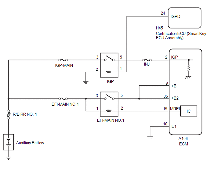
When the ignition switch is turned on (IG), the auxiliary battery voltage is applied to IGSW of the ECM. When the transistor in the MREL circuit operates, current flows from the auxiliary battery to ground through the drive circuit of the EFI-MAIN NO. 1 relay, thus operating the relay which supplies power to the +B and +B2 terminals of the ECM.
WIRING DIAGRAM
CAUTION / NOTICE / HINT
NOTICE:
Inspect the fuses for circuits related to this system before performing the following procedure.
PROCEDURE
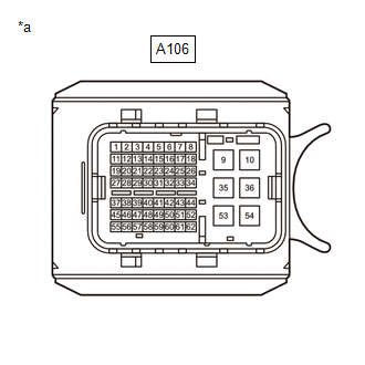
| 1. | CHECK HARNESS AND CONNECTOR (ECM - BODY GROUND) |
(a) Disconnect the ECM connector.
(b) Measure the resistance according to the value(s) in the table below.
Standard Resistance:
| Tester Connection | Condition | Specified Condition |
|---|---|---|
| A106-10(E1) - Body ground | Always | Below 1 Ω |
| NG |
 | REPAIR OR REPLACE HARNESS OR CONNECTOR |
|

| 2. | CHECK TERMINAL VOLTAGE (IGP TERMINAL VOLTAGE) |
(a) Disconnect the ECM connector.
(b) Turn the ignition switch to ON.
| (c) Measure the voltage according to the value(s) in the table below. Standard Voltage:
|
|
| NG |
 | GO TO STEP 6 |
|

| 3. | INSPECT EFI-MAIN NO. 1 RELAY |
Click here

| NG |
 | REPLACE EFI-MAIN NO. 1 RELAY |
|

| 4. | CHECK HARNESS AND CONNECTOR (EFI-MAIN NO. 1 RELAY - ECM) |
(a) Disconnect the ECM connector.
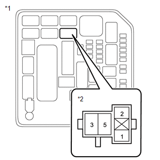
(b) Remove the EFI-MAIN NO. 1 relay, EFI-MAIN NO. 3 relay and EDU relay from the No. 1 engine room relay block assembly.
(c) Remove the EFI-MAIN NO. 2 relay from the No. 5 luggage room relay block assembly.
HINT:
Remove the EFI-MAIN NO. 2 and EFI-MAIN NO. 3 relays connected between the checked terminals as the coil inside the relay influences the measurement value.
(d) Measure the resistance according to the value(s) in the table below.
Standard Resistance:
| Tester Connection | Condition | Specified Condition |
|---|---|---|
| 2(EFI-MAIN NO.1 relay) - A106-15(MREL) | Always | Below 1 Ω |
| 5(EFI-MAIN NO.1 relay) - A106-9(+B) | Always | Below 1 Ω |
| 5(EFI-MAIN NO.1 relay) - A106-35(+B2) | Always | Below 1 Ω |
| 2(EFI-MAIN NO.1 relay) or A106-15(MREL) - Body ground and other terminals | Always | 10 kΩ or higher |
| 2(EFI-MAIN NO.1 relay), A106-15(MREL), A106-9(+B) or A106-35(+B2) - Body ground and other terminals | Always | 10 kΩ or higher |
| NG |
 | REPAIR OR REPLACE HARNESS OR CONNECTOR |
|

| 5. | CHECK TERMINAL VOLTAGE (POWER SOURCE OF EFI-MAIN NO. 1 RELAY) |
| (a) Remove the EFI-MAIN NO. 1 relay from the No. 1 engine room relay block assembly. |
|
(b) Measure the voltage according to the value(s) in the table below.
Standard Voltage:
| Tester Connection | Condition | Specified Condition |
|---|---|---|
| 1(EFI-MAIN NO. 1 relay) - Body ground | Always | 11 to 14 V |
| 3(EFI-MAIN NO. 1 relay) - Body ground | Always | 11 to 14 V |
| OK |
 | REPLACE ECM |
| NG |
 | REPAIR OR REPLACE HARNESS OR CONNECTOR (AUXILIARY BATTERY - EFI-MAIN NO. 1 RELAY) |
| 6. | INSPECT IGP RELAY |
Click here

| NG |
 | REPLACE INSTRUMENT PANEL JUNCTION BLOCK ASSEMBLY (IG2 D RELAY) |
|

| 7. | CHECK HARNESS AND CONNECTOR (IGP RELAY - ECM) |
(a) Disconnect the ECM connector.
(b) Remove the EFI-MAIN NO. 1 relay, EFI-MAIN NO. 3 relay and EDU relay from the No. 1 engine room relay block assembly.
(c) Remove the EFI-MAIN NO. 2 relay from the No. 5 luggage room relay block assembly.
HINT:
Remove the EFI-MAIN NO. 2 and EFI-MAIN NO. 3 relays connected between the checked terminals as the coil inside the relay influences the measurement value.
(d) Measure the resistance according to the value(s) in the table below.
Standard Resistance:
| Tester Connection | Condition | Specified Condition |
|---|---|---|
| 5(IGP relay) - A106-2(IGP) | Always | Below 1 Ω |
| 5(IGP relay) or A106-2(IGP) - Body ground and other terminals | Always | 10 kΩ or higher |
| NG |
 | REPAIR OR REPLACE HARNESS OR CONNECTOR |
|

| 8. | CHECK HARNESS AND CONNECTOR (POWER SOURCE VOLTAGE OF IGP RELAY) |
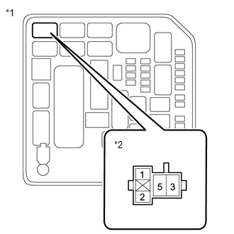
(a) Remove the IGP relay from the No. 1 engine room relay block assembly.
| (b) Measure the voltage according to the value(s) in the table below. Standard Voltage:
|
|
| NG |
 | REPAIR OR REPLACE HARNESS OR CONNECTOR (AUXILIARY BATTERY - INSTRUMENT PANEL JUNCTION BLOCK ASSEMBLY) |
|

| 9. | CHECK HARNESS AND CONNECTOR (IGP RELAY - BODY GROUND) |
(a) Remove the IGP relay from the No. 1 engine room relay block assembly.
(b) Measure the resistance according to the value(s) in the table below.
Standard Resistance:
| Tester Connection | Condition | Specified Condition |
|---|---|---|
| 2(IGP relay) - Body ground | Always | Below 1 Ω |
| NG |
 | REPAIR OR REPLACE HARNESS OR CONNECTOR |
|

| 10. | CHECK HARNESS AND CONNECTOR (CERTIFICATION ECU - IG2 D RELAY) |
(a) Disconnect the certification ECU (smart key ECU assembly) connector.
(b) Disconnect the instrument panel junction block assembly connector.
(c) Measure the resistance according to the value(s) in the table below.
Standard Resistance:
| Tester Connection | Condition | Specified Condition |
|---|---|---|
| H45-24(IGPD) - 1(IGP relay) | Always | Below 1 Ω |
| H45-24(IGPD) or 1(IGP relay) - Body ground and other terminals | Always | 10 kΩ or higher |
| OK |
 | GO TO ENTRY AND START SYSTEM (FOR START FUNCTION) |
| NG |
 | REPAIR OR REPLACE HARNESS OR CONNECTOR |
 Turbocharger Noise
DESCRIPTION HINT: Turbocharger noise is classified into two types. These are whistling sound and chattering sound. During troubleshooting, first determine the type of noise...
 VC Output Circuit
DESCRIPTION The ECM constantly generates a 5 V power source voltage from the auxiliary battery voltage supplied to the +B, +B2 (BATT) terminals to operate the microprocessor...
Other information:
Toyota Yaris XP210 (2020-2026) Reapir and Service Manual: Installation
INSTALLATION PROCEDURE 1. INSTALL RAIN SENSOR TAPE HINT: Only perform this procedure when replacing the rain sensor tape. Replace the rain sensor tape with new one if it is damaged or contaminated. (a) Clean the sensing portion of the rain sensor with a piece of cloth...
Toyota Yaris XP210 (2020-2026) Reapir and Service Manual: Driver Side Electrical Antenna Circuit Open (B27A113)
DESCRIPTION The certification ECU (smart key ECU assembly) generates a request signal and transmits the signal to the front door outside handle assembly LH (electrical key antenna) at intervals of 0.25 seconds. For the front door outside handle assembly LH (electrical key antenna) to detect when the electrical key transmitter sub-assembly is brought close to the vehicle, a signal requesting a response from the electrical key transmitter sub-assembly is transmitted within approximately 1 m (3...
Categories
- Manuals Home
- Toyota Yaris Owners Manual
- Toyota Yaris Service Manual
- Immobilizer System
- Headlights
- Adjustment
- New on site
- Most important about car
Fuel-Filler Lid and Cap
WARNING
When removing the fuel-filler cap, loosen the cap slightly and wait for any hissing to stop, then remove it
Fuel spray is dangerous. Fuel can burn skin and eyes and cause illness if ingested. Fuel spray is released when there is pressure in the fuel tank and the fuel-filler cap is removed too quickly.