Toyota Yaris: Sfi System / Turbocharger Noise
DESCRIPTION
HINT:
Turbocharger noise is classified into two types. These are whistling sound and chattering sound. During troubleshooting, first determine the type of noise.
| Type of Abnormal Noise | Outline of Abnormal Noise | Major Trouble Area |
|---|---|---|
| Whistling sound (airflow sound) | The whistling sound volume and pitch are proportional to the turbocharger or engine speed. The abnormal noise level becomes clear when the engine speed is increased. |
|
| Chattering sound (metallic sound) | The chattering sound pitch is lower than the whistling sound pitch. Has a comparatively constant pitch that is independent of the engine speed and vehicle speed. | Turbocharger HINT:
|
Faults and Symptoms of Engine Components
Turbocharger system| Main fault |
|
| Symptom |
|
| Main fault | Leak |
| Symptom | Abnormal noise during intake leak |
| Symptom | Gear noise HINT: The volume and pitch are proportional to the transmission gear speed. |
PROCEDURE
| 1. | CONFIRM CONDITION IN WHICH NOISE OCCURRED |
(a) Confirm with the customer the condition when noise occurred.
HINT:
To clearly understand the conditions in which the noise occurred, the items in the table below are useful.
| Item | Note |
|---|---|
| Engine speed | Engine speed range |
| Vehicle speed | Vehicle speed range |
| Transmission gear | Which gear? |
| Accelerator pedal position | During acceleration or deceleration? |
| Temperature |
|
| Road conditions |
|
| Noise level |
|
| Other symptoms |
|
| Noise recognition | What made the customer determine that the sound was a malfunction? |
| Proceed to |
| NEXT |
|

| 2. | CHECK DTC OUTPUT |
(a) Check the DTCs.
Powertrain > Engine > Trouble Codes| Result | Proceed to |
|---|---|
| DTC is not output | A |
| DTCs are output | B |
HINT:
- Check whether a DTC is stored related to the boost pressure sensor or atmospheric pressure sensor (in ECU).
- If a DTC is stored related to the boost pressure sensor or atmospheric pressure sensor (in ECU), defective actuator control related to the turbocharger may be the cause of the turbocharger noise.
| B |
 | GO TO DTC CHART |
|

| 3. | PERFORM SIMULATION TEST |
(a) Check whether the noise described by the customer occurs.
HINT:
If an abnormal noise is heard, check whether it matches the noise described by the customer.
(b) If an abnormal noise is confirmed, determine which system emits it.
| Result | Proceed to |
|---|---|
| Noise occurs (ticking or rattling (metallic sound) during idling) | A |
| Noise occurs (squealing (metallic sound) when driving) | B |
| Noise occurs (hissing (airflow sound) when driving) | C |
| Noise occurs (whistling or foghorn-like (airflow sound) during acceleration or deceleration) | D |
| The noise described by the customer could not be confirmed. | E |
HINT:
Perform "Inspection After Repair" after replacing the turbocharger sub-assembly.
Click here

| A |
 | REPLACE TURBOCHARGER SUB-ASSEMBLY |
| C |
 | GO TO STEP 8 |
| D |
 | GO TO STEP 12 |
| E |
 | GO TO STEP 17 |
|

| 4. | CHECK TURBOCHARGER SUB-ASSEMBLY |
(a) Check that the turbine shaft rotates smoothly, without catching.
Click here

(b) Check for loose turbine mounting nuts and for axial play in the turbine shaft.
Click here

HINT:
If the turbine shaft catches or if there no play or excessive play, it could indicate poor sliding due to seal damage due to seizing or a deposit build-up.
Standard value:
0.10 mm (0.00394 in.) or less
| Result | Proceed to |
|---|---|
| No turbine shaft malfunction | A |
| Turbine shaft malfunction | B |
HINT:
Perform "Inspection After Repair" after replacing the turbocharger sub-assembly.
Click here

| B |
 | REPLACE TURBOCHARGER SUB-ASSEMBLY |
|

| 5. | CHECK TURBOCHARGER SUB-ASSEMBLY |
(a) Check for damage to the compressor impeller.
(b) Check for interference between the compressor impeller and the compressor housing.
| Result | Proceed to |
|---|---|
| No damage or interference | A |
| Damage or interference exists | B |
HINT:
Perform "Inspection After Repair" after replacing the turbocharger sub-assembly.
Click here

| B |
 | REPLACE TURBOCHARGER SUB-ASSEMBLY |
|

| 6. | REPLACE TURBOCHARGER SUB-ASSEMBLY |
Click here

|

| 7. | PERFORM SIMULATION TEST |
(a) Check that the abnormal noise has disappeared.
| NEXT |
 | END |
| 8. | CHECK TURBOCHARGER SUB-ASSEMBLY |
(a) Check that no soot or oil adheres to the turbocharger sub-assembly connectors.
HINT:
If adhering soot or an oil leak exists, air leaking at that position may be the cause of the abnormal noise.
| Result | Proceed to |
|---|---|
| No adhering soot or an oil | A |
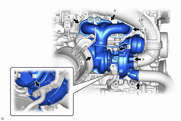
| Soot adhering around the turbine housing, flange, or V band (A in the illustration) | B |
| Oil leak from the contact surface between the compressor housing and the seal plate or between the seal plate and the bearing housing (B in the illustration) | |
| Oil adhering to the compressor flange (C in the illustration) | C |
HINT:
Perform "Inspection After Repair" after replacing the turbocharger sub-assembly.
Click here

| B |
 | REPLACE TURBOCHARGER SUB-ASSEMBLY |
| C |
 | GO TO STEP 11 |
|

| 9. | REPLACE TURBOCHARGER SUB-ASSEMBLY |
Click here

|

| 10. | PERFORM SIMULATION TEST |
(a) Check that the abnormal noise has disappeared.
| NEXT |
 | END |
| 11. | REPAIR OR REPLACE DEFECTIVE PARTS (PARTS LEAKING OIL) |
(a) Repair or replace the parts that are leaking oil.
HINT:
- If oil leaks from the contact surface between the compressor inlet elbow and the compressor housing, the installation may be incorrect due to loose nuts or a defective gasket. Check the installation or replace the gasket.
- If oil leaks from the contact surface between the compressor outlet elbow and the compressor housing, the installation may be incorrect due to loose nuts or a defective gasket. Check the installation or replace the gasket.
| NEXT |
 | END |
| 12. | CHECK TURBOCHARGER SUB-ASSEMBLY |
(a) Check that the turbine shaft rotates smoothly, without catching.
Click here

(b) Check for loose turbine mounting nuts and for axial play in the turbine shaft.
Click here

HINT:
If the turbine shaft catches or if there no play or excessive play, it could indicate poor sliding due to seal damage due to seizing or a deposit build-up.
Standard value:
0.10 mm (0.00394 in.) or less
| Result | Proceed to |
|---|---|
| No turbine shaft malfunction | A |
| Turbine shaft malfunction | B |
HINT:
Perform "Inspection After Repair" after replacing the turbocharger sub-assembly.
Click here

| B |
 | REPLACE TURBOCHARGER SUB-ASSEMBLY |
|

| 13. | CHECK TURBOCHARGER SUB-ASSEMBLY |
(a) Check for damage to the compressor impeller.
(b) Check for interference between the compressor impeller and the compressor housing.
HINT:
If the previous checks find no malfunction, replace the compressor with bearing housing sub-assembly and determine if the noise improved.
| Result | Proceed to |
|---|---|
| No damage or interference | A |
| Damage or interference exists | B |
HINT:
Perform "Inspection After Repair" after replacing the turbocharger sub-assembly.
Click here

| B |
 | REPLACE TURBOCHARGER SUB-ASSEMBLY |
|

| 14. | REPLACE TURBOCHARGER SUB-ASSEMBLY |
Click here

|

| 15. | PERFORM SIMULATION TEST |
(a) Check that the abnormal noise has disappeared.
| Result | Proceed to |
|---|---|
| Abnormal noise has disappeared | A |
| Noise occurs (whistling sound) | B |
| A |
 | END |
|

| 16. | CHECK GEAR NOISE |
(a) Check if the gear noise is the source of the abnormal noise (not the noise from the turbocharger).
| NEXT |
 | ELIMINATE THE CAUSE OF THE NOISE |
| 17. | EXPLAIN TO CUSTOMER THAT SOUND IS NORMAL |
(a) Explain to the customer that the sound described by the customer is not a malfunction.
HINT:
To convince the customer, it is helpful to drive the customer in a different vehicle.
| NEXT |
 | END |
 Turbocharger Oil Leak and White Smoke
DESCRIPTION Type of Oil Leak Outline Major Trouble Area Internal oil leak (white smoke) Oil leak from the bearing housing into the compressor housing (intake side) or turbine housing (exhaust side) through the seal ring...
 ECM Power Source Circuit
DESCRIPTION When the ignition switch is turned on (IG), the auxiliary battery voltage is applied to IGSW of the ECM. When the transistor in the MREL circuit operates, current flows from the auxiliary battery to ground through the drive circuit of the EFI-MAIN NO...
Other information:
Toyota Yaris XP210 (2020-2026) Reapir and Service Manual: Park/Neutral Switch Circuit Short to Ground (P085011,P085015)
DESCRIPTION The engine stop and start ECU detects a malfunction by comparing the shift position signal with the neutral position switch signal input state. If a malfunction is detected, the engine stop and start ECU blinks the stop and start cancel indicator light, prohibits the stop and start control and stores DTC P085011 or P085015...
Toyota Yaris XP210 (2020-2026) Reapir and Service Manual: Inspection
INSPECTION PROCEDURE 1. CHECK CANISTER (FUEL SUCTION WITH PUMP AND GAUGE TUBE ASSEMBLY) (a) Visually check the canister (fuel suction with pump and gauge tube assembly). (1) Visually check the canister (fuel suction with pump and gauge tube assembly) for cracks or damage...
Categories
- Manuals Home
- Toyota Yaris Owners Manual
- Toyota Yaris Service Manual
- Brake System Control Module "A" System Voltage System Voltage Low (C137BA2)
- To Set Speed
- Fuse Panel Description
- New on site
- Most important about car
Key Suspend Function
If a key is left in the vehicle, the functions of the key left in the vehicle are temporarily suspended to prevent theft of the vehicle.
To restore the functions, press the unlock button on the functions-suspended key in the vehicle.