Toyota Yaris: Sfi System / Starter Relay Circuit Short to Battery (P061512)
MONITOR DESCRIPTION
While the engine is cranked, current flows from terminal STA2 of the engine stop and start ECU to terminal STA of the ECM (STA signal). If the ECM detects the starter control (STA) signal while the vehicle is being driven, it determines that there is a malfunction in the STA circuit. The ECM then illuminates the MIL and stores this DTC.
This monitor runs when the vehicle is driven at 20 km/h (12.43 mph) or more for 20 seconds or more.
| DTC No. | Detection Item | DTC Detection Condition | Trouble Area | MIL | Note |
|---|---|---|---|---|---|
| P061512 | Starter Relay Circuit Short to Battery | All of the following conditions are met, and auxiliary battery voltage of 10.5 V or higher is applied to the ECM for 20 seconds (1 trip detection logic):
|
| Comes on | SAE: P0617 |
MONITOR STRATEGY
| Frequency of Operation | Continuous |
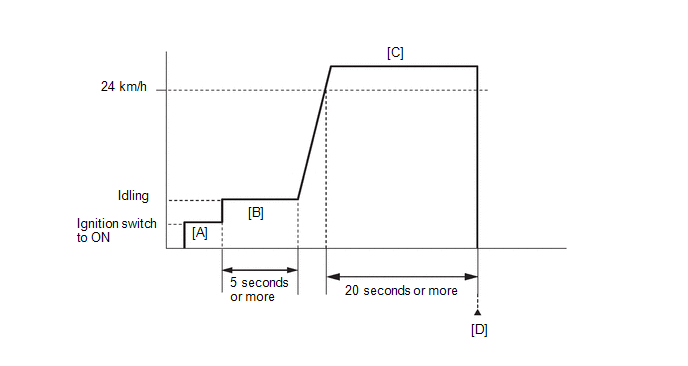
CONFIRMATION DRIVING PATTERN
- Connect the GTS to the DLC3.
- Turn the ignition switch to ON.
- Turn the GTS on.
- Clear the DTCs (even if no DTCs are stored, perform the clear DTC procedure).
- Turn the ignition switch off and wait for at least 30 seconds.
- Turn the ignition switch to ON [A].
- Turn the GTS on.
- Start the engine.
- Idle the engine for 5 seconds or more [B].
-
Drive the vehicle at a speed of 24 km/h (15 mph) or more for 20 seconds or more [C].
CAUTION:
When performing the confirmation driving pattern, obey all speed limits and traffic laws.
- Enter the following menus: Powertrain / Engine / Trouble Codes [D].
-
Read the pending DTCs.
HINT:
- If a pending DTC is output, the system is malfunctioning.
- If a pending DTC is not output, perform the following procedure.
- Enter the following menus: Powertrain / Engine / Utility / All Readiness.
- Input the DTC: P061512.
-
Check the DTC judgment result.
GTS Display
Description
NORMAL
- DTC judgment completed
- System normal
ABNORMAL
- DTC judgment completed
- System abnormal
INCOMPLETE
- DTC judgment not completed
- Perform driving pattern after confirming DTC enabling conditions
HINT:
- If the judgment result is NORMAL, the system is normal.
- If the judgment result is ABNORMAL, the system has a malfunction.
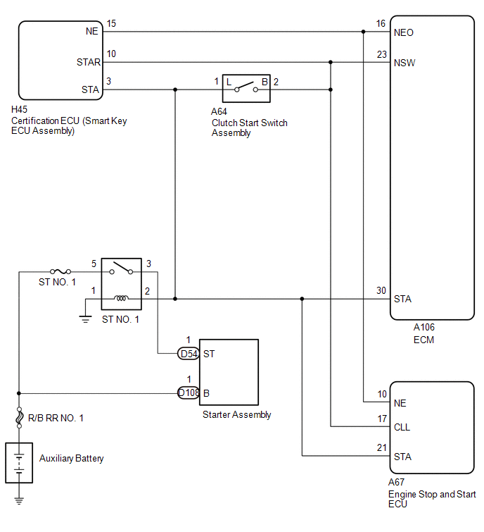
WIRING DIAGRAM
CAUTION / NOTICE / HINT
HINT:
Read Freeze Frame Data using the GTS. The ECM records vehicle and driving condition information as Freeze Frame Data the moment a DTC is stored. When troubleshooting, Freeze Frame Data can help determine if the vehicle was moving or stationary, if the engine was warmed up or not, if the air fuel ratio was lean or rich, and other data from the time the malfunction occurred.
NOTICE:
Inspect the fuses for circuits related to this system before performing the following procedure.
- Inspect the fuses for circuits related to this system before performing the following procedure.
-
After turning ignition switch off, waiting time may be required before disconnecting the cable from the negative (-) auxiliary battery terminal. Therefore, make sure to read the disconnecting the cable from the negative (-) auxiliary battery terminal notices before proceeding with work.
Click here

-
When the starter assembly is replaced, the number of starter operations stored in the engine stop and start ECU must be reset.
Click here

- When the starter assembly is replaced, "ST NO. 1 relay" must be also replaced.
PROCEDURE
| 1. | READ VALUE USING GTS (STARTER SW) |
(a) Enter the following menus.
Powertrain > Engine > Data List| Tester Display |
|---|
| Starter SW |
(b) According to the display on the GTS, read the Data List.
Standard:
| Condition | Starter SW |
|---|---|
| Ignition switch ON | OFF |
(c) According to the display on the GTS, read the Data List while the vehicle is being driven with an engine speed of 1000 rpm or more at a vehicle speed of 20 km/h (12.43 mph) or more.
CAUTION:
When performing the confirmation driving pattern, obey all speed limits and traffic laws.
Standard:
| Condition | Starter SW |
|---|---|
| Driving at 20 km/h (12.43 mph) or more (engine speed 1000 rpm or more) | OFF |
HINT:
If the result of either of the above is not as specified, proceed to the next step with the ignition switch to ON, GTS connected and Data List item "Starter SW" selected.
| Result | Proceed to |
|---|---|
| OK | A |
| NG | B |
HINT:
If the starter assembly operates continuously when the ignition switch is turned to ON, proceed to the next step without reading the Data List item "Starter SW".
| A |
 | CHECK FOR INTERMITTENT PROBLEMS |
|

| 2. | INSPECT ST NO. 1 RELAY (CHECK FOR SHORT CIRCUIT) |
(a) Enter the following menus.
Powertrain > Engine > Data List| Tester Display |
|---|
| Starter SW |
(b) Remove the ST NO. 1 relay from the No. 1 engine room relay block assembly.
(c) According to the display on the GTS, read the Data List.
| Result | Proceed to |
|---|---|
| The Data List item "Starter SW" does not change from ON | A |
| The Data List item "Starter SW" changes from ON to OFF | B |
HINT:
- When the result of the above inspection is "The Data List item "Starter SW" does not change from ON", the ST NO. 1 relay is normal.
- DTCs may be stored during this inspection. Check for DTCs and clear them using the GTS.
| B |
 | REPLACE ST NO. 2 RELAY |
|

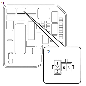
| 3. | CHECK TERMINAL VOLTAGE (POWER SOURCE OF ST NO. 1 RELAY) |

| *1 | No. 1 Engine Room Relay Block Assembly |
| *2 | ST NO. 1 Relay |
HINT:
The purpose of this step is to check for ST NO. 1 relay terminal voltage under abnormal conditions.
(a) Remove the ST NO. 1 relay from the No. 1 engine room relay block assembly.
(b) Turn the ignition switch to ON.
(c) Measure the voltage between ST NO. 1 relay terminal 2 and body ground.
HINT:
- Make a note of the measured voltage as it will be necessary for the inspecting the change in voltage in the next step. As the next step should be conducted under the same conditions, keep the ignition switch to ON and do not install the ST NO. 1 relay.
- DTCs may be stored during this inspection. Check for DTCs and clear them using the GTS.
-
If any voltage was measured with the ignition switch to ON, one of the following malfunctions is suspected:
- Short to +B in the circuit of a connected ECU or the switch.
- Short to +B in the wire harness.
|

| 4. | INSPECT ENGINE STOP AND START ECU (CHECK FOR SHORT CIRCUIT) |

| *1 | No. 1 Engine Room Relay Block Assembly |
| *2 | ST NO. 1 Relay |
(a) Disconnect the engine stop and start ECU connector.
(b) Measure the voltage between ST NO. 1 relay terminal 2 and body ground and compare it to the voltage measured in the previous step.
| Result | Proceed to |
|---|---|
| The voltage between ST NO. 1 relay terminal 2 and body ground does not change when the connector is disconnected. | A |
| The voltage between ST NO. 1 relay terminal 2 and body ground changes when the connector is disconnected. | B |
HINT:
- If the voltage is the same before and after disconnecting the connector, the engine stop and start ECU is normal.
- DTCs may be stored during this inspection. Check for DTCs and clear them using the GTS.
| B |
 | REPLACE ENGINE STOP AND START ECU |
|

| 5. | INSPECT CLUTCH START SWITCH ASSEMBLY (CHECK FOR SHORT CIRCUIT) |

| *1 | No. 1 Engine Room Relay Block Assembly |
| *2 | ST NO. 1 Relay |
(a) Disconnect the clutch start switch assembly connector.
(b) Measure the voltage between ST NO. 1 relay terminal 2 and body ground and compare it to the voltage measured in the previous step.
| Result | Proceed to |
|---|---|
| The voltage between ST NO. 1 relay terminal 2 and body ground does not change when the connector is disconnected. | A |
| The voltage between ST NO. 1 relay terminal 2 and body ground changes when the connector is disconnected. | B |
HINT:
- If the voltage is the same before and after disconnecting the connector, the clutch pedal switch assembly is normal.
- DTCs may be stored during this inspection. Check for DTCs and clear them using the GTS.
| B |
 | REPLACE CLUTCH START SWITCH ASSEMBLY |
|

| 6. | INSPECT ECM (CHECK FOR SHORT CIRCUIT) |
| *1 | No. 1 Engine Room Relay Block Assembly |
| *2 | ST NO. 1 Relay |
(a) Disconnect the ECM connector.
(b) Measure the voltage between ST NO. 1 relay terminal 2 and body ground and compare it to the voltage measured in the previous step.
| Result | Proceed to |
|---|---|
| The voltage between ST NO. 1 relay terminal 2 and body ground does not change when the connector is disconnected. | A |
| The voltage between ST NO. 1 relay terminal 2 and body ground changes when the connector is disconnected. | B |
HINT:
- If the voltage is the same before and after disconnecting the connector, the ECM is normal.
- DTCs may be stored during this inspection. Check for DTCs and clear them using the GTS.
| B |
 | REPLACE ECM |
|

| 7. | CHECK HARNESS AND CONNECTOR (ECM - PARK/NEUTRAL POSITION SWITCH ASSEMBLY - CERTIFICATION ECU - ST NO. 1 RELAY) |
(a) Disconnect the ECM connector.
(b) Disconnect the clutch start switch assembly connector.
(c) Disconnect the certification ECU (smart key ECU assembly) connector.
(d) Remove the ST NO. 1 relay from the No. 1 engine room relay block assembly.
(e) Disconnect the engine stop and start ECU connector.
(f) Measure the resistance according to the value(s) in the table below.
Standard Resistance:
| Tester Connection | Condition | Specified Condition |
|---|---|---|
| A106-30 (STA), A64-5 (L), H45-3 (STA), A67-21 (STA) or 2 (ST NO. 1 relay) - Other terminals | Always | 10 kΩ or higher |
| OK |
 | CHECK ENTRY AND START SYSTEM (CHECK FOR STA TERMINAL VOLTAGE OF SMART KEY ECU ASSEMBLY) |
| NG |
 | REPAIR OR REPLACE HARNESS OR CONNECTOR |
 Internal Control Module Throttle Position Performance Internal Electronic Failure (P060E49)
MONITOR DESCRIPTION The ECM monitors the signals received from the No. 1 throttle position sensor. As the ECM monitors the VTA1 signal of the No. 1 throttle position sensor, if these signals do not correlate, a DTC will be stored...
 Fuel Pump "A" Control Circuit Short to Battery (P062712)
DESCRIPTION The fuel pump control ECU performs PWM (Pulse Width Modulation) control to control the fuel pump (for low pressure side) speed steplessly over a wide range...
Other information:
Toyota Yaris XP210 (2020-2026) Reapir and Service Manual: Terminals Of Ecu
TERMINALS OF ECU NOTICE: DTCs may be output when connectors are disconnected during inspection. Therefore, be sure to clear the DTCs using the GTS once the inspection has been completed. Do not apply excessive force to the forward recognition camera connector...
Toyota Yaris XP210 (2020-2026) Reapir and Service Manual: Tire Repair Seal
DisposalDISPOSAL PROCEDURE 1. DISPOSE OF TIRE REPAIR SEAL HINT: Confirm the expiration date on the side of the repair seal bottle. (a) Dispose of the retrieved seal by consigning disposal to a waste disposal firm. NOTICE: The valve and valve core cannot be reused...
Categories
- Manuals Home
- Toyota Yaris Owners Manual
- Toyota Yaris Service Manual
- Brake System Control Module "A" System Voltage System Voltage Low (C137BA2)
- G16e-gts (engine Mechanical)
- Headlights
- New on site
- Most important about car
Supplemental Restraint System (SRS) Precautions
The front and side supplemental restraint systems (SRS) include different types of air bags. Please verify the different types of air bags which are equipped on your vehicle by locating the “SRS AIRBAG” location indicators. These indicators are visible in the area where the air bags are installed.
The air bags are installed in the following locations:
The steering wheel hub (driver air bag) The front passenger dashboard (front passenger air bag) The outboard sides of the front seatbacks (side air bags) The front and rear window pillars, and the roof edge along both sides (curtain air bags)