Toyota Yaris: Meter / Gauge System / Speedometer Malfunction
DESCRIPTION
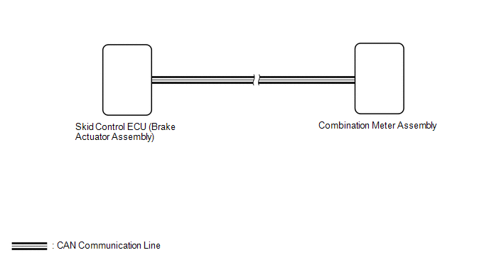
The combination meter assembly receives vehicle speed signals from the skid control ECU (brake actuator assembly) via CAN communication. The speed sensor detects the wheel speed and sends the appropriate signals to the skid control ECU (brake actuator assembly). The skid control ECU (brake actuator assembly) supplies power to the vehicle speed sensor. The skid control ECU (brake actuator assembly) detects vehicle speed signals based on pulses of the voltage.
HINT:
Factors that affect the indicated vehicle speed include the tire size, tire inflation, and tire wear. The speed indicated on the speedometer has an allowable margin of error.
WIRING DIAGRAM
CAUTION / NOTICE / HINT
NOTICE:
- When replacing the combination meter assembly, always replace it with a new one. If a combination meter assembly which was installed to another vehicle is used, the information stored in it will not match the information from the vehicle and a DTC may be stored.
-
Before starting the following inspection, inspect the speedometer and check that the tire size and air pressure are as specified.
Tire size and air pressure: Click here

Speedometer: Click here

PROCEDURE
| 1. | CHECK CAN COMMUNICATION SYSTEM |
(a) Check if CAN communication DTCs are output.
Click here

| Result | Proceed to |
|---|---|
| DTCs are not output | A |
| DTCs are output | B |
| B |
 | GO TO CAN COMMUNICATION SYSTEM |
|

| 2. | CHECK FOR DTC (VEHICLE STABILITY CONTROL SYSTEM) |
(a) Check if vehicle stability control system DTCs are output.
Chassis > Brake > Trouble Codes| Result | Proceed to |
|---|---|
| DTCs are not output | A |
| DTCs are output | B |
| B |
 | GO TO VEHICLE STABILITY CONTROL SYSTEM |
|

| 3. | PERFORM ACTIVE TEST USING GTS |
(a) Perform the Active Test according to the display on the GTS.
Body Electrical > Combination Meter > Active Test| Tester Display | Measurement Item | Control Range | Diagnostic Note |
|---|---|---|---|
| Speedometer Operation (0km/h,0MPH) | Speedometer (0 km/h, 0 mph) | ON | When this Active Test is performed, an operation signal is sent directly to the combination meter assembly to operate the speedometer. |
| Speedometer Operation (40km/h,40MPH) | Speedometer (40 km/h, 40 mph) | ON |
|
| Speedometer Operation (80km/h,80MPH) | Speedometer (80 km/h, 80 mph) | ON |
|
| Speedometer Operation (120km/h,120MPH) | Speedometer (120 km/h, 120 mph) | ON |
|
| Speedometer Operation (160km/h,160MPH) | Speedometer (160 km/h, 160 mph) | ON |
|
| Speedometer Operation (200km/h,200MPH) | Speedometer (200 km/h, 200 mph) | ON |
|
| Speedometer Operation (240km/h,240MPH) | Speedometer (240 km/h, 240 mph) | ON | When this Active Test is performed, an operation signal is sent directly to the combination meter assembly to operate the speedometer. |
-
*1: For the tolerance of each Speed Signal Input Active Test, refer to On-vehicle Inspection.
Click here

| Tester Display |
|---|
| Speedometer Operation (0km/h,0MPH) |
| Tester Display |
|---|
| Speedometer Operation (40km/h,40MPH) |
| Tester Display |
|---|
| Speedometer Operation (80km/h,80MPH) |
| Tester Display |
|---|
| Speedometer Operation (120km/h,120MPH) |
| Tester Display |
|---|
| Speedometer Operation (160km/h,160MPH) |
| Tester Display |
|---|
| Speedometer Operation (200km/h,200MPH) |
| Tester Display |
|---|
| Speedometer Operation (240km/h,240MPH) |
OK:
Speedometer indication is normal.
HINT:
When the value of the Active Test is more than or equal to the speedometer upper limit, the indicated speed stops at the upper limit.
| OK |
 | REPLACE SKID CONTROL ECU (BRAKE ACTUATOR ASSEMBLY) |
| NG |
 | REPLACE COMBINATION METER ASSEMBLY |
 Entire Combination Meter does not Operate
DESCRIPTION This circuit is the power source circuit for the combination meter assembly. This circuit provides two types of power sources; one is a constant power source, and the other is an IG power source...
 Tachometer Malfunction
DESCRIPTION In this circuit, the combination meter assembly receives engine speed signals from the ECM via CAN communication. The combination meter assembly displays the engine speed calculated based on the data received from the ECM...
Other information:
Toyota Yaris XP210 (2020-2026) Reapir and Service Manual: How To Proceed With Troubleshooting
CAUTION / NOTICE / HINT HINT: Before performing troubleshooting for the dynamic radar cruise control system, perform troubleshooting for the pre-collision system. Click here *: Use the GTS. PROCEDURE 1. VEHICLE BROUGHT TO WORKSHOP NEXT 2...
Toyota Yaris XP210 (2020-2026) Owner's Manual: Rear Door Child Safety Locks
These locks are intended to help prevent children from accidentally opening the rear doors. Use them on both rear doors whenever a child rides in the rear seat of the vehicle. Unlock Lock If you slide the child safety lock to the lock position before closing that door, the door cannot be opened from the inside...
Categories
- Manuals Home
- Toyota Yaris Owners Manual
- Toyota Yaris Service Manual
- Key Battery Replacement
- Immobilizer System
- To Set Speed
- New on site
- Most important about car
Break-In Period
No special break-in is necessary, but a few precautions in the first 600 miles (1,000 km) may add to the performance, economy, and life of the vehicle.
Do not race the engine. Do not maintain one constant speed, either slow or fast, for a long period of time. Do not drive constantly at full-throttle or high engine rpm for extended periods of time. Avoid unnecessary hard stops. Avoid full-throttle starts.