Toyota Yaris: Meter / Gauge System / Entire Combination Meter does not Operate
DESCRIPTION
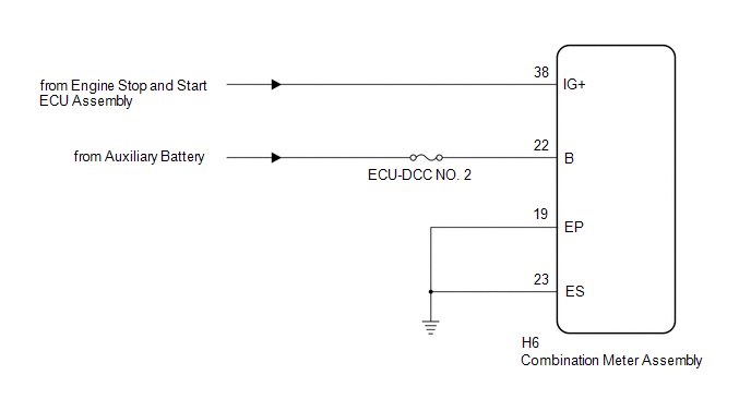
This circuit is the power source circuit for the combination meter assembly. This circuit provides two types of power sources; one is a constant power source, and the other is an IG power source.
WIRING DIAGRAM
CAUTION / NOTICE / HINT
NOTICE:
- When replacing the combination meter assembly, always replace it with a new one. If a combination meter assembly which was installed to another vehicle is used, the information stored in it will not match the information from the vehicle and a DTC may be stored.
- Inspect the fuses of circuits related to this system before performing the following procedure.
PROCEDURE
| 1. | CHECK HARNESS AND CONNECTOR (POWER SOURCE CIRCUIT) |
(a) Disconnect the H6 combination meter assembly connector.
(b) Measure the resistance according to the value(s) in the table below.
Standard Resistance:
| Tester Connection | Condition | Specified Condition |
|---|---|---|
| H6-19 (EP) - Body ground | Always | Below 1 Ω |
| H6-23 (ES) - Body ground | Always | Below 1 Ω |
(c) Measure the voltage according to the value(s) in the table below.
Standard Voltage:
| Tester Connection | Switch Condition | Specified Condition |
|---|---|---|
| H6-38 (IG+) - Body ground | Ignition switch off | Below 1 V |
| Ignition switch ON | 10.5 to 16 V | |
| H6-22 (B) - Body ground | Ignition switch off | 11 to 14 V |
| OK |
 | REPLACE COMBINATION METER ASSEMBLY |
| NG |
 | REPAIR OR REPLACE HARNESS OR CONNECTOR |
 Lost Communication With ECM/PCM "A" Missing Message (U010087,U011487,U012987,U013187,U014087,U015187,U016887,U023587,U023A87,U111287,U113387)
DESCRIPTION The combination meter assembly communicates with each ECU via CAN communication. DTC No. Detection Item DTC Detection Condition Trouble Area U010087 Lost Communication With ECM/PCM "A" Missing Message Diagnosis Condition:
The ignition switch is ON
IG power source voltage is 9...
 Speedometer Malfunction
DESCRIPTION The combination meter assembly receives vehicle speed signals from the skid control ECU (brake actuator assembly) via CAN communication. The speed sensor detects the wheel speed and sends the appropriate signals to the skid control ECU (brake actuator assembly)...
Other information:
Toyota Yaris XP210 (2020-2026) Reapir and Service Manual: Removal
REMOVAL PROCEDURE 1. DISCONNECT NO. 1 ROOF HEADLINING MOULDING LH Click here 2. DISCONNECT NO. 1 ROOF HEADLINING MOULDING RH HINT: Use the same procedure as for the LH side. 3. REMOVE FRONT PILLAR GARNISH LH Click here 4. REMOVE FRONT PILLAR GARNISH RH HINT: Use the same procedure as for the LH side...
Toyota Yaris XP210 (2020-2026) Reapir and Service Manual: Excessive Brake Pedal Travel (No Fluid Leaks and No Air in System)
CAUTION / NOTICE / HINT NOTICE: After replacing the skid control ECU (brake actuator assembly), perform "Calibration". Click here PROCEDURE 1. PRE-INSPECTION (a) Brake pedal inspection (1) Perform a visual inspection and operate the brake pedal to check for any malfunctions...
Categories
- Manuals Home
- Toyota Yaris Owners Manual
- Toyota Yaris Service Manual
- Brake System Control Module "A" System Voltage System Voltage Low (C137BA2)
- Key Battery Replacement
- How to connect USB port/Auxiliary jack
- New on site
- Most important about car
Fuel Gauge
The fuel gauge shows approximately how much fuel is remaining in the tank when the ignition is switched ON. We recommend keeping the tank over 1/4 full.
