Toyota Yaris: Spiral Cable / Inspection
INSPECTION
PROCEDURE
1. INSPECT SPIRAL CABLE SUB-ASSEMBLY
NOTICE:
- Do not remove the steering sensor from the spiral cable sub-assembly when inspecting the spiral cable sub-assembly.
- Remove the steering sensor from the spiral cable sub-assembly only when replacing the spiral cable sub-assembly.
(a) Visually check the spiral cable sub-assembly for defects.
(1) The defects are as follows:
- Scratches
- Small cracks
- Dents
- Chips
-
Cracks or other damage to the connector
OK:
No defects are found.
If any of the defects is found, replace the spiral cable sub-assembly with a new one.
(b) Check the spiral cable sub-assembly.
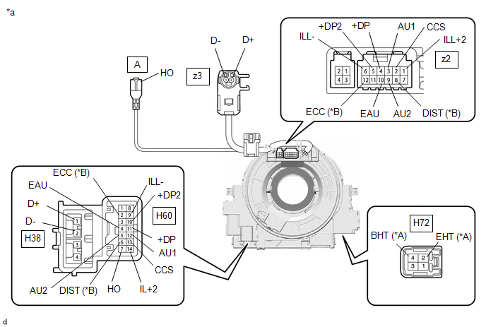
| *A | w/ Heated Steering Wheel System | *B | w/ Lane tracing assist system and Dynamic radar cruise control system |
| *a | Component without harness connected (Spiral Cable Sub-assembly) | - | - |
 | Interlock | - | - |
NOTICE:
- When rotating the spiral cable sub-assembly, make sure to push on the interlock shown in the illustration to release the interlock mechanism.
- As the spiral cable sub-assembly may break, do not rotate the spiral cable sub-assembly more than the specified amount.
(1) Set the spiral cable sub-assembly to the center position.
Click here

(2) Measure the resistance between each terminal of the spiral cable sub-assembly according to the value(s) in the table below.
(3) After setting the spiral cable sub-assembly to the center position, rotate the spiral cable sub-assembly 2.5 times clockwise, and measure the resistance according to the value(s) in the table below. Then rotate the spiral cable sub-assembly 5 times counterclockwise, and measure the resistance according to the value(s) in the table below.
(4) After setting the spiral cable sub-assembly to the center position, rotate the spiral cable sub-assembly 2.5 times clockwise. Then while rotating the spiral cable sub-assembly 5 times counterclockwise, measure the resistance according to the value(s) in the table below.
Standard Resistance:
| Tester Connection | Condition | Specified Condition |
|---|---|---|
| H60-2(ECC) - z2-12(ECC) | Always | 3 Ω or less |
| H60-4(EAU) - z2-10(EAU) | Always | 3 Ω or less |
| H60-5(AU2) - z2-9(AU2) | Always | 3 Ω or less |
| H60-6(DIST) - z2-8(DIST) | Always | 3 Ω or less |
| H60-7(HO) - A(HO) | Always | 3 Ω or less |
| H60-9(ILL-) - z2-6(ILL-) | Always | 3 Ω or less |
| H60-10(+DP2) - z2-5(+DP2) | Always | 3 Ω or less |
| H60-11(+DP) - z2-4(+DP) | Always | 3 Ω or less |
| H60-12(AU1) - z2-3(AU1) | Always | 3 Ω or less |
| H60-13(CCS) - z2-2(CCS) | Always | 3 Ω or less |
| H60-14(IL+2) - z2-1(IL+2) | Always | 3 Ω or less |
| H38-1(D+) - z3-2(D+) | Always | Below 1 Ω |
| H38-2(D-) - z3-1(D-) | Always | Below 1 Ω |
| H72-2(EHT) - Z16-1(EHT) | Always | Below 1 Ω |
| H72-4(BHT) - Z16-4(BHT) | Always | Below 1 Ω |
If the result is not as specified, replace the spiral cable sub-assembly.
 Removal
REMOVAL CAUTION / NOTICE / HINT The necessary procedures (adjustment, calibration, initialization or registration) that must be performed after parts are removed, installed or replaced during the spiral cable with sensor sub-assembly removal/installation are shown below...
 Installation
INSTALLATION PROCEDURE 1. INSPECT SPIRAL CABLE WITH SENSOR SUB-ASSEMBLY (a) Check that the spiral cable with sensor sub-assembly is center position. OK: The connector is at the top...
Other information:
Toyota Yaris XP210 (2020-2026) Owner's Manual: Headlights
Without auto-light control Turn the headlight switch to turn the headlights, other exterior lights and dashboard illumination on or off. * 1: The lights are turned on while the vehicle is driven. * 2: The lights are turned on for the specified period by the auto headlight off function...
Toyota Yaris XP210 (2020-2026) Reapir and Service Manual: Diagnostic Trouble Code Chart
D..
Categories
- Manuals Home
- Toyota Yaris Owners Manual
- Toyota Yaris Service Manual
- Engine Start Function When Key Battery is Dead
- Brake System Control Module "A" System Voltage System Voltage Low (C137BA2)
- Auto Lock/Unlock Function
- New on site
- Most important about car
Fuel Gauge
The fuel gauge shows approximately how much fuel is remaining in the tank when the ignition is switched ON. We recommend keeping the tank over 1/4 full.
