Toyota Yaris: Spiral Cable / Removal
REMOVAL
CAUTION / NOTICE / HINT
The necessary procedures (adjustment, calibration, initialization or registration) that must be performed after parts are removed, installed or replaced during the spiral cable with sensor sub-assembly removal/installation are shown below.
CAUTION:
Be sure to read precaution thoroughly before servicing.
Click here

NOTICE:
After turning the ignition switch off, waiting time may be required before disconnecting the cable from the negative (-) auxiliary battery terminal.
Click here

HINT:
When the cable is disconnected / reconnected to the auxiliary battery terminal, systems temporarily stop operating. However, each system has a function that completes learning the first time the system is used.
-
Learning completes when vehicle is driven
Effect/Inoperative Function When Necessary Procedures are not Performed
Necessary Procedures
Link
Lane tracing assist system
Drive the vehicle straight ahead at 35 km/h (22 mph) or more for 5 seconds or more.

Pre-collision system
Parking support brake system
Stop and start system
Drive the vehicle until stop and start control is permitted (approximately 5 to 60 minutes)

-
Learning completes when vehicle is operated normally
Effect/Inoperative Function When Necessary Procedures are not Performed
Necessary Procedures
Link
Power door lock control system
- Back door opener
Perform door unlock operation with door control switch or electrical key transmitter sub-assembly switch.

Air conditioning system
After the ignition switch is turned to ON, the servo motor standard position is recognized.
-
PROCEDURE
1. REMOVE HORN BUTTON ASSEMBLY
Click here

2. REMOVE STEERING WHEEL ASSEMBLY
Click here

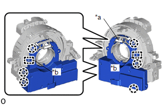
3. INSPECT SPIRAL CABLE WITH SENSOR SUB-ASSEMBLY
(a) Check that the front wheels are facing straight ahead.
(b) Check that the spiral cable with sensor sub-assembly is center position.
OK:
The connector is at the top.
The colored roller or the top of the flat cable U-turn can be checked from the check window.
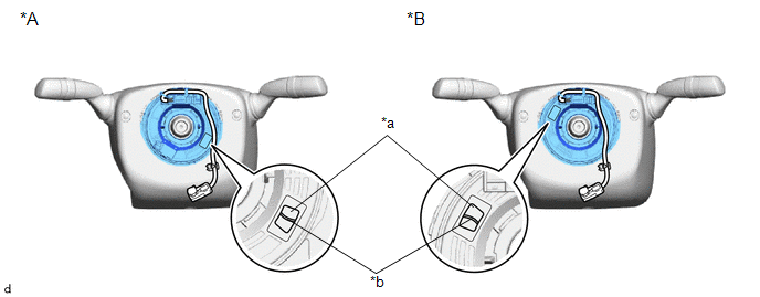
| *A | w/ Heated Steering Wheel System | *B | w/o Heated Steering Wheel System |
| *a | Check Window | *b | Top of Flat Cable U-turn |
NOTICE:
If the result is not as specified, it is possible that the spiral cable sub-assembly is broken. Replace the spiral cable sub-assembly with a new one.
4. REMOVE LOWER STEERING COLUMN COVER
Click here

5. REMOVE UPPER STEERING COLUMN COVER
Click here

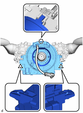
6. REMOVE SPIRAL CABLE WITH SENSOR SUB-ASSEMBLY
NOTICE:
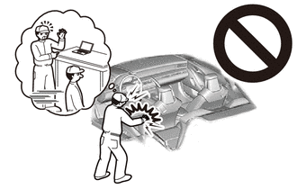
- Do not replace the spiral cable with sensor sub-assembly with the battery connected and the ignition switch on (IG).
- Do not rotate the spiral cable with sensor sub-assembly with the battery connected and the ignition switch on (IG).
- When rotating the spiral cable with sensor sub-assembly to check the operation of the spiral cable with sensor sub-assembly (checking for abnormal noise, checking the Data List, etc.), make sure to perform the inspection with the steering wheel assembly installed.
(a) Disconnect each connector.
NOTICE:
When disconnecting any airbag connector, take care not to damage the airbag wire harness.
HINT:
Refer to How to Connect or Disconnect Airbag Connector: Click here

| (b) Disengage the claw and clips to remove the spiral cable with sensor sub-assembly. |
|
7. REMOVE STEERING SENSOR
NOTICE:
- Remove the steering sensor from the spiral cable sub-assembly only when replacing the spiral cable sub-assembly.
- Removing the steering sensor from the spiral cable sub-assembly without using a lock pin may result in a misaligned center position of the steering sensor. Therefore, make sure to use the lock pin provided with a new spiral cable when removing the steering sensor from the spiral cable sub-assembly.
| (a) Install the lock pin to the steering sensor. NOTICE:
|
|
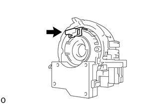
| (b) Disengage the claws and guides to remove the steering sensor from the spiral cable sub-assembly. |
|
 Components
C..
 Inspection
INSPECTION PROCEDURE 1. INSPECT SPIRAL CABLE SUB-ASSEMBLY NOTICE:
Do not remove the steering sensor from the spiral cable sub-assembly when inspecting the spiral cable sub-assembly...
Other information:
Toyota Yaris XP210 (2020-2026) Reapir and Service Manual: Glass Position Initialization Incomplete (B2313)
DESCRIPTION The power window regulator motor assemblies are operated by the multiplex network master switch assembly or power window regulator switch assembly. The power window regulator motor assemblies have motor, regulator and ECU functions. When the ECU built into a power window regulator motor assembly determines that the power window regulator motor assemblies have not been initialized, DTC B2313 is stored...
Toyota Yaris XP210 (2020-2026) Reapir and Service Manual: Quarter Trim Speaker
ComponentsCOMPONENTS ILLUSTRATION *1 REAR SPEAKER ASSEMBLY - - RemovalREMOVAL CAUTION / NOTICE / HINT HINT: Use the same procedure for the RH and LH sides. The procedure listed below is for the LH side. PROCEDURE 1. REMOVE QUARTER TRIM PANEL ASSEMBLY Click here 2...
Categories
- Manuals Home
- Toyota Yaris Owners Manual
- Toyota Yaris Service Manual
- Opening and Closing the Liftgate/Trunk Lid
- Engine Start Function When Key Battery is Dead
- Diagnostic Trouble Code Chart
- New on site
- Most important about car
Fuel-Filler Lid and Cap
WARNING
When removing the fuel-filler cap, loosen the cap slightly and wait for any hissing to stop, then remove it
Fuel spray is dangerous. Fuel can burn skin and eyes and cause illness if ingested. Fuel spray is released when there is pressure in the fuel tank and the fuel-filler cap is removed too quickly.