Toyota Yaris: Sfi System / Brake Override System
DESCRIPTION
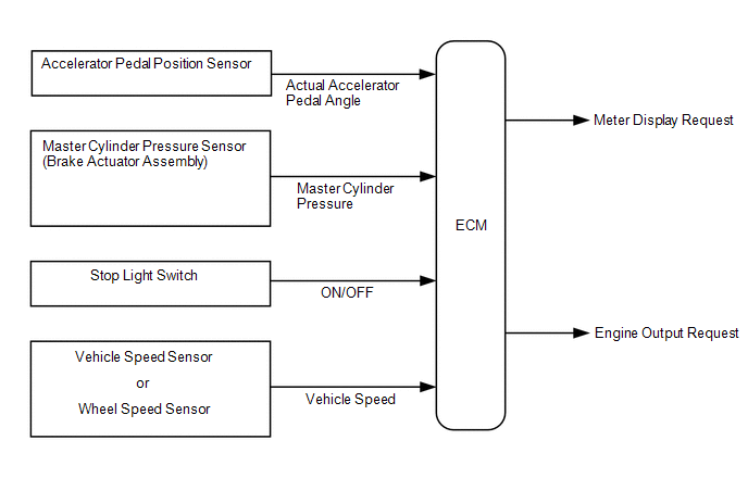
When the vehicle is being driven, depressing the accelerator pedal sensor assembly and brake pedal will activate the brake override system to restrict engine output. The conditions for activating the brake override system as well as the items that are controlled are explained below.
 Activation Conditions:
 -
When the accelerator pedal and brake pedal are depressed.
NOTICE:
The vehicle may not enter the brake override system control due to the relation of the accelerator pedal angle and the vehicle's speed.
-
When the vehicle speed is extremely low, the accelerator opening value used when controlling the engine is reduced more than normal.
HINT:
During control, the Accelerator Position value in the Data List will be lower than normal.
-
When the vehicle speed is not extremely low, the accelerator opening value is forcibly lowered to a fixed value.
HINT:
- During control, the Accelerator Position value in the Data List is forcibly reduced to a specified value regardless of the actual accelerator opening value (Accelerator Position Sensor No.1 Voltage %).
- During brake override system control, the operation indicator is displayed on the meter.
- When the brake pedal or the accelerator pedal returns to some degree.
CAUTION / NOTICE / HINT
Inspection MethodExample:
Drive at 10 km/h (6.25 mph), depress the accelerator pedal by 1/2 to 3/4 and keep it in that position. Under these conditions, if the engine speed decreases to 1000 rpm when the brake pedal is depressed, then the brake override system has been activated.
CAUTION:
When carrying out the inspection, use a place where you are able to carry it out safely and also pay close attention to your surroundings.
Also, when driving make absolutely sure that all road traffic laws, such as speed limits, are observed.
HINT:
-
Under normal conditions, the Accelerator Position value changes in response to the Accelerator Position Sensor No.1 Voltage % value. For more information on the numerical values, refer to the Data List.
Click here

- If the Accelerator Position and Accelerator Position Sensor No.1 Voltage % values in the Data List diverge and the Accelerator Position value in the Data List is fixed even though Accelerator Position Sensor No.1 Voltage % is changing, check that this control is activated (use the GTS data saving function to record data while driving the vehicle and then confirm it after driving is completed).
NOTICE:
The brake override system restricts engine output if the brake pedal is depressed when driving with the accelerator pedal depressed. If a customer reports experiencing loss of torque after the accelerator and brake pedals have both been intentionally depressed, explain to the customer that this is not a malfunction, and that the customer should avoid depressing both the accelerator and brake pedals at the same time.
Example: While operating the accelerator pedal, the customer uses their left foot to operate the brake pedal.
PROCEDURE
| 1. | CHECK DTC OUTPUT |
(a) Perform the Health Check using the GTS.
(b) Check the DTCs.
| Result | Proceed to |
|---|---|
| DTCs are not output | A |
| DTCs are output | B |
| B |
 | GO TO DTC CHART |
|

| 2. | READ VALUE USING GTS (MASTER CYLINDER SENSOR 1) |
(a) Start the engine.
(b) Read the value displayed on the GTS.
Chassis > Brake > Data List| Tester Display |
|---|
| Master Cylinder Sensor 1 |
Standard:
-1.00 to 0.00 MPa (Brake pedal released).
(c) Check that the brake fluid pressure value of the "Master Cylinder Sensor 1" observed on the GTS changes when the brake pedal is depressed.
OK:
When the pedal is depressed, the pressure displayed on the GTS increases.
| NG |
 | CHECK BRAKE ACTUATOR ASSEMBLY |
|

| 3. | READ VALUE USING GTS (STOP LIGHT SW) |
(a) Check the Data List indication when the brake pedal is depressed and released.
Powertrain > Engine > Data List| Tester Display |
|---|
| Stop Light SW |
OK:
| GTS Display | Condition | Specified Condition |
|---|---|---|
| Stop Light SW | Brake pedal released | OFF |
| Brake pedal depressed | ON |
| NG |
 | INSPECT STOP LIGHT SWITCH ASSEMBLY |
|

| 4. | INSPECT BRAKE PEDAL SUPPORT ASSEMBLY |
(a) Inspect and adjust the brake pedal support assembly.
HINT:
If the stop light switch turns ON too late, the start of brake override system control may be delayed; if it turns ON too soon, brake override system control may begin too early, so conduct inspection of the brake pedal support assembly and stop light switch assembly.
| NG |
 | REPAIR OR REPLACE BRAKE PEDAL SUPPORT ASSEMBLY |
|

| 5. | READ VALUE USING GTS (ACCELERATOR PEDAL POSITION SENSOR) |
(a) Read the value displayed on the GTS.
Powertrain > Engine > Data List| Tester Display |
|---|
| Accelerator Position Sensor No.1 Voltage % |
| Accelerator Position Sensor No.2 Voltage % |
Standard:
| GTS Display | Condition | Specified Condition |
|---|---|---|
| Accelerator Position Sensor No.1 Voltage % | Accelerator Pedal Released → Depressed → Released | Values smoothly change following accelerator pedal operation |
| Accelerator Position Sensor No.2 Voltage % |
HINT:
For numerical values of Accelerator Position Sensor No.1 Voltage % and Accelerator Position Sensor No.2 Voltage %, refer to the Data List.
Click here

| NG |
 | REPLACE ACCELERATOR PEDAL SENSOR ASSEMBLY |
|

| 6. | READ VALUE USING GTS (VEHICLE SPEED) |
(a) Start the engine.
(b) Read the value displayed on the GTS.
Powertrain > Engine > Data List| Tester Display |
|---|
| Vehicle Speed |
Standard:
| GTS Display | Condition | Specified Condition |
|---|---|---|
| Vehicle Speed | Vehicle stopped, engine running | 0 km/h (0 mph) |
| Vehicle being driven at constant speed between 16.1 to 64.4 km/h (10 to 40 mph) | No large fluctuations when driving at a constant speed |
CAUTION:
When performing a drive test, obey all speed limits and traffic laws.
HINT:
Data can be captured relatively easily by using the snapshot function in the Data List. Confirm the data after performing the drive test.
| NG |
 | GO TO METER / GAUGE SYSTEM (SPEED SIGNAL CIRCUIT) |
|

| 7. | READ VALUE USING GTS (FR, FL, RR, RL WHEEL SPEED) |
(a) Start the engine.
(b) Read the value displayed on the GTS.
Chassis > Brake > Data List| Tester Display |
|---|
| FR Wheel Speed |
| FL Wheel Speed |
| RR Wheel Speed |
| RL Wheel Speed |
Standard:
| GTS Display | Condition | Specified Condition |
|---|---|---|
| FR Wheel Speed FL Wheel Speed RR Wheel Speed RL Wheel Speed | Vehicle stopped, engine running | 0 km/h (0 mph) |
| Vehicle being driven at constant speed between 16.1 to 64.4 km/h (10 to 40 mph) | No large fluctuations when driving at a constant speed |
CAUTION:
When performing a drive test, obey all speed limits and traffic laws.
HINT:
Data can be captured relatively easily by using the snapshot function in the Data List. Confirm the data after performing the drive test.
| OK |
 | END |
| NG |
 | INSPECT FRONT OR REAR SPEED SENSOR |
 Starter Signal Circuit
DESCRIPTION While the engine is being cranked, current flows from terminal STAR of the certification ECU (smart key ECU assembly) to the clutch start switch assembly and to terminal STA of the ECM (STA signal)...
 MIL Circuit
DESCRIPTION The Malfunction Indicator Lamp (MIL) is used to indicate vehicle malfunctions detected by the ECM. The MIL operation can be checked visually...
Other information:
Toyota Yaris XP210 (2020-2026) Reapir and Service Manual: Clutch Position Sensor "A"Circuit Short to Battery (P080512,P080514)
DESCRIPTION The clutch pedal stroke sensor assembly is mounted on the clutch pedal, and detects the clutch pedal position and sends signals to the ECM. DTC No. Detection Item DTC Detection Condition Trouble Area MIL Memory Note P080512 Clutch Position Sensor "A"Circuit Short to Battery Clutch stroke sensor signal voltage is 4...
Toyota Yaris XP210 (2020-2026) Reapir and Service Manual: How To Proceed With Troubleshooting
CAUTION / NOTICE / HINT HINT: Replace parts related to the wireless door lock and smart key system according to the inspection procedure. If the wireless door lock and smart key system does not operate, first check the customize item and make sure that the wireless door lock and smart key system is not turned off...
Categories
- Manuals Home
- Toyota Yaris Owners Manual
- Toyota Yaris Service Manual
- Key Battery Replacement
- Battery Monitor Module General Electrical Failure (P058A01)
- Brake System Control Module "A" System Voltage System Voltage Low (C137BA2)
- New on site
- Most important about car
Turning the Engine Off
Stop the vehicle completely. Manual transaxle: Shift into neutral and set the parking brake.Automatic transaxle: Shift the selector lever to the P position and set the parking brake.
Press the push button start to turn off the engine. The ignition position is off.