Toyota Yaris: Sfi System / MIL Circuit
DESCRIPTION
The Malfunction Indicator Lamp (MIL) is used to indicate vehicle malfunctions detected by the ECM.
The MIL operation can be checked visually. When the ignition switch is first turned to ON, the MIL should be illuminated and should then turn off after the engine is started. If the MIL remains illuminated or is not illuminated, conduct the following troubleshooting procedure using the GTS.
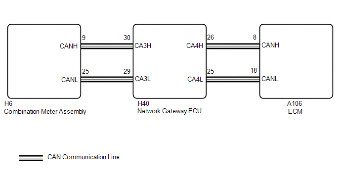
WIRING DIAGRAM
PROCEDURE
| 1. | CHECK THAT MIL IS ILLUMINATED |
(a) Perform troubleshooting in accordance with the table below.
| MIL | Condition | Proceed to |
|---|---|---|
| Illuminates → Turns off | Ignition switch ON → engine is started | A |
| Other than above | - | B |
| A |
 | CHECK FOR INTERMITTENT PROBLEMS |
|

| 2. | CHECK COMMUNICATION BETWEEN GTS AND ECM |
(a) Check the communication between the GTS and ECM.
HINT:
It can be checked using the "Engine" item of the Data List.
| Result | Proceed to |
|---|---|
| Communication is possible | A |
| Communication is not possible | B |
| B |
 | GO TO VC OUTPUT CIRCUIT |
|

| 3. | CHECK WHETHER DTC OUTPUT RECURS |
(a) Perform the Health Check using the GTS.
(b) Check if any DTCs have been detected. Note down any DTCs.
| Result | Proceed to |
|---|---|
| DTCs are not output | A |
| Any DTCs is output | B |
HINT:
Check for detected DTCs output from other ECUs which relate to the MIL.
| B |
 | REPAIR CIRCUIT INDICATED BY OUTPUT |
|

| 4. | PERFORM ACTIVE TEST USING GTS |
(a) Check the status of the MIL while performing the Active Test.
Body Electrical > Combination Meter > Active Test| Tester Display |
|---|
| Check Engine Warning |
| Result | Proceed to |
|---|---|
| Changes | A |
| Does not change | B |
| A |
 | REPLACE ECM |
| B |
 | REPLACE COMBINATION METER ASSEMBLY |
 Brake Override System
DESCRIPTION When the vehicle is being driven, depressing the accelerator pedal sensor assembly and brake pedal will activate the brake override system to restrict engine output...
 Ignition Circuit
DESCRIPTION A direct ignition system is used on this vehicle. The direct ignition system is a 1 cylinder ignition system which ignites one cylinder with one ignition coil...
Other information:
Toyota Yaris XP210 (2020-2026) Reapir and Service Manual: Fuel Lid Lock Control Cable Assembly
ComponentsCOMPONENTS ILLUSTRATION *1 FUEL LID LOCK OPEN LEVER SUB-ASSEMBLY *2 FUEL FILLER OPENING LID LOCK RETAINER *3 FUEL LID LOCK CONTROL CABLE SUB-ASSEMBLY - - RemovalREMOVAL PROCEDURE 1. REMOVE FRONT SEAT ASSEMBLY (for Driver Side) Click here 2...
Toyota Yaris XP210 (2020-2026) Reapir and Service Manual: Barometric Pressure - Turbocharger/Supercharger Inlet Pressure Correlation Bank 1 Signal Compare Failure (P006D62)
DESCRIPTION The E.F.I. vacuum sensor assembly is installed upstream of the turbocharger compressor and measures the air inlet duct internal pressure with a built-in sensor. At ignition switch to ON or during idling, the E.F.I. vacuum sensor assembly and the atmospheric pressure sensor built into the ECM are at atmospheric pressure and their output match...
Categories
- Manuals Home
- Toyota Yaris Owners Manual
- Toyota Yaris Service Manual
- Diagnostic Trouble Code Chart
- Fuse Panel Description
- Engine & Hybrid System
- New on site
- Most important about car
Front Seat Belt Pretensioners
The front seat belt pretensioners are designed to deploy in moderate or severe frontal, near frontal collisions.
In addition, the pretensioners operate when a side collision or a rollover accident is detected. The pretensioners operate differently depending on what types of air bags are equipped. For more details about the seat belt pretensioner operation, refer to the SRS Air Bag Deployment Criteria.