Toyota Yaris: Stop And Start System / Clutch Pedal Switch "A" Circuit Short to Ground (P083011)
DESCRIPTION
HINT:
This DTC is applicable to Manual Transaxle models only.
The clutch stroke sensor assembly (for detecting pedal depression amount) and clutch switch assembly (for detecting the pedal depression endpoint) are installed to the clutch pedal. When the engine is stopped by stop and start control, the engine stop and start control ECU receives the clutch pedal depression start signal from the clutch stroke sensor, and starts the engine.
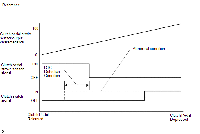
When the engine stop and start control ECU detects the clutch stroke sensor ON signal and clutch switch ON signal are input simultaneously for 1.2 seconds or more, it stores a DTC and flashes the stop and start cancel indicator light.
HINT:
The normal signal conditions are as shown in the table below.
| Signal | Clutch Pedal Released | In Transition | Clutch Pedal Depressed |
|---|---|---|---|
| Clutch pedal stroke sensor | ON | OFF | OFF |
| Clutch switch | OFF | OFF | ON |
The ECM receives the ON and OFF signals from the clutch stroke sensor, and sends them to the engine stop and start control ECU using CAN communication.
| DTC No. | Detection Item | DTC Detection Condition | Trouble Area | Warning Indicate | Memory | Note |
|---|---|---|---|---|---|---|
| P083011 | Clutch Pedal Switch "A" Circuit Short to Ground | Conditions (a) and (b) are met for 1.2 seconds or more (1 trip detection logic): (a) Ignition switch ON (b) Clutch switch is on when Clutch pedal stroke sensor signal is on. |
| Blinks | DTC stored | SAE Code: P0830 |
CONFIRMATION DRIVING PATTERN
HINT:
DTCs for the stop and start system are not cleared even automatically if the malfunction has been repaired. After repairing the malfunction, be sure to clear the DTCs.
Click here

HINT:
-
If the cable is disconnected from the battery terminal, stop and start control is prohibited until refresh charge is completed.
In this case, let the vehicle idle to complete the refresh charge. The refresh charge is complete when the Data List item "Status of Battery Charge Control" changes from "Refresh Charge Mode". (Usually, idling the engine for 5 to 60 minutes with the battery temperature at 11°C (51°F) or higher, the refresh charge will be completed.)
-
If the GTS is not available and the Data List item "Status of Battery Charge Control" cannot be checked, charge the battery by idling the engine for approximately 5 to 60 minutes or driving the vehicle, and then drive the vehicle and check that stop and start control operates.
If the engine is started with the hood open, the system determines that a jump start has occurred. Therefore, make sure that the hood is closed before starting the engine and driving the vehicle.
- After the refresh charge completes, turn the ignition switch off, wait for at least 30 seconds, and then start the engine again. If the vehicle enters refresh charge mode again while the engine is idling, the initial refresh charge did not properly complete, so wait for the refresh charge to complete.
CONFIRMATION AFTER TROUBLESHOOTING
(a) Connect the GTS to the DLC3.
(b) Turn the ignition switch to ON and turn the GTS on.
(c) Clear the DTCs.
Click here

(d) Start the engine.
(e) Fully depress the clutch pedal for 1 second or more. Release the clutch pedal and wait for at least 1 second.
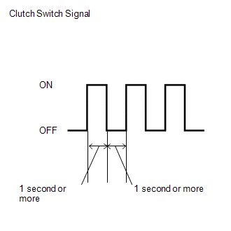
(f) Repeat the previous step 3 times.
(g) Check that no DTCs are output.
Click here

HINT:
-
If the cable is disconnected from the battery terminal, stop and start control is prohibited until refresh charge is completed.
In this case, let the vehicle idle to complete the refresh charge. The refresh charge is complete when the Data List item "Status of Battery Charge Control" changes from "Refresh Charge Mode". (Usually, idling the engine for 5 to 60 minutes with the battery temperature at 11°C (51°F) or higher, the refresh charge will be completed.)
-
If the GTS is not available and the Data List item "Status of Battery Charge Control" cannot be checked, charge the battery by idling the engine for approximately 5 to 60 minutes or driving the vehicle, and then drive the vehicle and check that stop and start control operates.
If the engine is started with the hood open, the system determines that a jump start has occurred. Therefore, make sure that the hood is closed before starting the engine and driving the vehicle.
- After the refresh charge completes, turn the ignition switch off, wait for at least 30 seconds, and then start the engine again. If the vehicle enters refresh charge mode again while the engine is idling, the initial refresh charge did not properly complete, so wait for the refresh charge to complete.
STOP AND START SYSTEM OPERATION CHECK
(a) Start the engine and warm it up.
(b) Turn the air conditioning system off.
(c) Drive the vehicle at 7 km/h (4 mph) or more.
CAUTION:
When performing Confirmation Driving Pattern, obey all speed limits and traffic laws.
(d) Stop the vehicle, move the shift lever to neutral and release the clutch pedal.
(e) Allow the engine to stop by stop and start control.
(f) Depress the clutch pedal and start the engine.
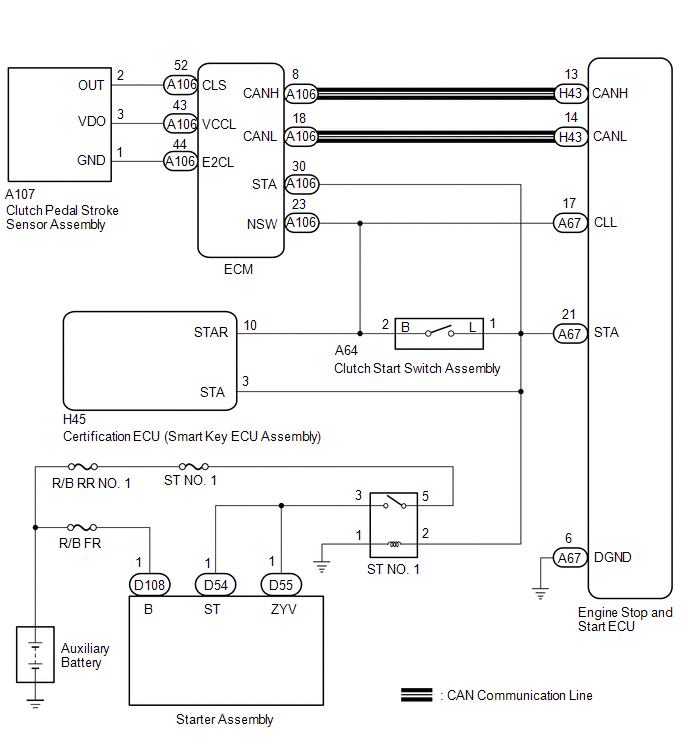
WIRING DIAGRAM
CAUTION / NOTICE / HINT
NOTICE:
-
Before replacing the engine stop and start ECU, read the number of starter operations and write it into a new engine stop and start ECU.
Click here

-
After replacing the engine stop and start ECU or air conditioning amplifier assembly, reset and perform learning of the air conditioning information in the engine stop and start ECU.
Click here

-
After replacing the engine stop and start ECU or airbag sensor assembly, clear and calibrate the deceleration sensor zero point in the engine stop and start ECU.
Click here

HINT:
Using the GTS, read the freeze frame data before troubleshooting. System condition information is recorded as freeze frame data the moment a DTC is stored. This information can be useful when troubleshooting.
Click here

PROCEDURE
| 1. | READ VALUE USING GTS (CLUTCH LOWER SWITCH) |
| Tester Display |
|---|
| Clutch Lower Switch |
(a) Depress the clutch pedal and read the values displayed on the GTS.
OK:
| Tester Display | Condition | Normal Condition |
|---|---|---|
| Clutch Lower Switch | Fully Depressed | ON |
| Clutch Lower Switch | Fully Released | OFF |
| OK |
 | USE SIMULATION METHOD TO CHECK |
|

| 2. | INSPECT CLUTCH START SWITCH ASSEMBLY |
Click here

| NG |
 | REPLACE CLUTCH START SWITCH ASSEMBLY |
|

| 3. | CHECK HARNESS AND CONNECTOR (ENGINE STOP AND START ECU - CLUTCH START SWITCH ASSEMBLY) |
(a) Disconnect the A67 engine stop and start ECU connector.
(b) Disconnect the A64 clutch start switch assembly connector.
(c) Disconnect the H45 certification ECU (smart key ECU assembly) connector.
(d) Disconnect the A106 ECM connector.
(e) Measure the resistance according to the value(s) in the table below.
Standard Resistance:
| Tester Connection | Condition | Specified Condition |
|---|---|---|
| A67-17 (CLL) - A64-1 (L) | Always | Below 1 Ω |
| A67-17 (CLL) - Body ground | Always | 10 kΩ or higher |
| A64-1 (L) - Body ground | Always | 10 kΩ or higher |
| OK |
 | REPLACE ENGINE STOP AND START ECU |
| NG |
 | REPAIR OR REPLACE HARNESS OR CONNECTOR |
 Starter Relay Signal Compare Failure (P061562)
DESCRIPTION When the STA signal detected by the ECM and by the engine stop and start ECU do not match, the engine stop and start ECU stores DTC P061562 and blinks the stop and start cancel indicator...
 Park/Neutral Switch Circuit Short to Ground (P085011,P085015)
DESCRIPTION The engine stop and start ECU detects a malfunction by comparing the shift position signal with the neutral position switch signal input state...
Other information:
Toyota Yaris XP210 (2020-2026) Owner's Manual: Location of the Tire Label (Placard)
You will find the tire label containing tire inflation pressure by tire size and other important information on the driver’s side B-pillar or on the edge of the driver’s door frame. SAMPLE Recommended Tire Inflation Pressure On the tire label you will find the recommended tire inflation pressure in both kPa and psi for the tires installed as original equipment on the vehicle...
Toyota Yaris XP210 (2020-2026) Reapir and Service Manual: Precaution
PRECAUTION HANDLING PRECAUTION FOR DYNAMIC RADAR CRUISE CONTROL SYSTEM Keep in mind the following points when servicing vehicles equipped with the dynamic radar cruise control system. (a) The dynamic radar cruise control system is designed to be used when driving on highways and freeways...
Categories
- Manuals Home
- Toyota Yaris Owners Manual
- Toyota Yaris Service Manual
- Opening and Closing the Liftgate/Trunk Lid
- Maintenance
- Fuel Gauge
- New on site
- Most important about car
Fuel-Filler Lid and Cap
WARNING
When removing the fuel-filler cap, loosen the cap slightly and wait for any hissing to stop, then remove it
Fuel spray is dangerous. Fuel can burn skin and eyes and cause illness if ingested. Fuel spray is released when there is pressure in the fuel tank and the fuel-filler cap is removed too quickly.