Toyota Yaris: Vacuum Pump / Components
COMPONENTS
ILLUSTRATION
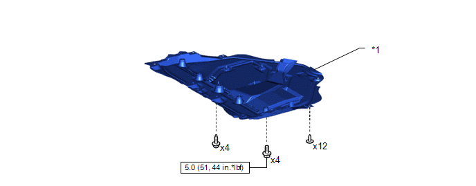
| *1 | NO. 1 ENGINE UNDER COVER ASSEMBLY | - | - |
 | N*m (kgf*cm, ft.*lbf): Specified torque | - | - |
ILLUSTRATION
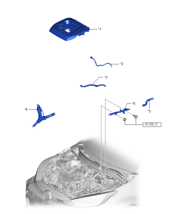
| *1 | NO. 1 ENGINE COVER SUB-ASSEMBLY | *2 | FUEL TUBE SUB-ASSEMBLY |
| *3 | NO. 1 FUEL VAPOR FEED HOSE | *4 | ENGINE WIRE |
| *5 | OUTLET HEATER WATER HOSE | *6 | NO. 1 WATER BY-PASS PIPE |
 | N*m (kgf*cm, ft.*lbf): Specified torque | - | - |
ILLUSTRATION
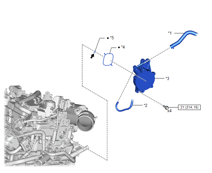
| *1 | UNION TO CONNECTOR TUBE HOSE | *2 | NO. 3 VACUUM TRANSMITTING HOSE |
| *3 | VACUUM PUMP ASSEMBLY | *4 | NO. 2 O-RING |
| *5 | NO. 4 O-RING | - | - |
 | N*m (kgf*cm, ft.*lbf): Specified torque | ● | Non-reusable part |
 | Engine Oil | - | - |
 Vacuum Pump
..
 On-vehicle Inspection
ON-VEHICLE INSPECTION PROCEDURE 1. REMOVE NO. 1 ENGINE COVER SUB-ASSEMBLY Click here
2. DISCONNECT UNION TO CONNECTOR TUBE HOSE Click here
3. OPERATION CHECK (a) Connect the hose of the vacuum gauge to the vacuum pump assembly...
Other information:
Toyota Yaris XP210 (2020-2026) Reapir and Service Manual: Data List / Active Test
DATA LIST / ACTIVE TEST NOTICE: In the table below, the values listed under "Normal Condition" are reference values. Do not depend solely on these reference values when deciding whether a part is faulty or not. When using the GTS with the ignition switch off, connect the GTS to the DLC3 and turn a courtesy light switch on and off at intervals of 1...
Toyota Yaris XP210 (2020-2026) Reapir and Service Manual: Fuel Pump Control Circuit
DESCRIPTION The fuel pump circuit consists of the ECM, fuel pump and fuel pump control ECU (which operates the fuel pump). Based on the engine output, the ECM determines the fuel pump speed. The speed is then converted to a duty signal and sent to the fuel pump control ECU...
Categories
- Manuals Home
- Toyota Yaris Owners Manual
- Toyota Yaris Service Manual
- G16e-gts (engine Mechanical)
- Adjustment
- How to use USB mode
- New on site
- Most important about car
Supplemental Restraint System (SRS) Precautions
The front and side supplemental restraint systems (SRS) include different types of air bags. Please verify the different types of air bags which are equipped on your vehicle by locating the “SRS AIRBAG” location indicators. These indicators are visible in the area where the air bags are installed.
The air bags are installed in the following locations:
The steering wheel hub (driver air bag) The front passenger dashboard (front passenger air bag) The outboard sides of the front seatbacks (side air bags) The front and rear window pillars, and the roof edge along both sides (curtain air bags)