Toyota Yaris: Stop And Start System / Park/Neutral Switch Circuit Short to Ground (P085011,P085015)
DESCRIPTION
The engine stop and start ECU detects a malfunction by comparing the shift position signal with the neutral position switch signal input state. If a malfunction is detected, the engine stop and start ECU blinks the stop and start cancel indicator light, prohibits the stop and start control and stores DTC P085011 or P085015.
| DTC No. | Detection Item | DTC Detection Condition | Trouble Area | Warning Indicate | Memory | Note |
|---|---|---|---|---|---|---|
| P085011 | Park/Neutral Switch Circuit Short to Ground | The following condition continues for 1 second or more (1 trip detection logic)
|
| Blinking | DTC stored | SAE Code: P0851 |
| P085015 | Park/Neutral Switch Circuit Short to Battery or Open | The following condition continues for 1 second or more (1 trip detection logic)
|
| Blinking | DTC stored | SAE Code: P0852 |
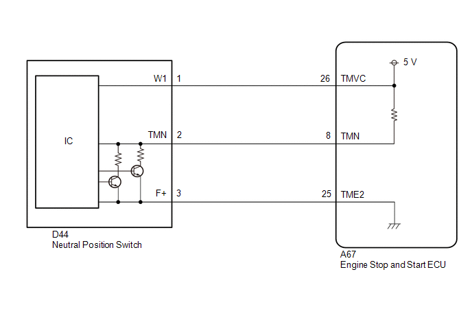
WIRING DIAGRAM
CAUTION / NOTICE / HINT
NOTICE:
-
Before replacing the engine stop and start ECU, read the number of starter operations and write it into a new engine stop and start ECU.
Click here

-
After replacing the engine stop and start ECU, perform learning of the external backup boost converter (eco run vehicle converter assembly).
Click here

-
After replacing the engine stop and start ECU or air conditioning amplifier assembly, reset and perform learning of the air conditioning information in the engine stop and start ECU.
Click here

-
When the ECM is replaced on a vehicle with a non-specified auxiliary battery, it is necessary to perform auxiliary battery type switching.
Click here

- Inspect the fuses for circuits related to this system before performing the following procedure.
HINT:
-
Using the GTS, read the freeze frame data before troubleshooting. System condition information is recorded as freeze frame data the moment a DTC is stored. This information can be useful when troubleshooting.
Click here

-
For wire harness and connector inspection procedures and precautions, refer to

-
DTCs for the stop and start system are not cleared even if the malfunction has been repaired. After repairing the malfunction, be sure to clear the DTCs.
Click here

PROCEDURE
| 1. | READ VALUE USING GTS (NEUTRAL SWITCH) |
| Tester Display |
|---|
| Neutral Switch |
(a) Read the value when the shift lever is in neutral and any other position.
OK:
| Tester Display | Condition | Normal Condition |
|---|---|---|
| Neutral Switch | Shift lever in neutral | ON |
| Neutral Switch | Shift lever in any position other than neutral | OFF |
| OK |
 | USE SIMULATION METHOD TO CHECK |
|

| 2. | CHECK HARNESS AND CONNECTOR (ENGINE STOP AND START ECU - NEUTRAL POSITION SWITCH) |
(a) Disconnect the A67 engine stop and start ECU connector.
(b) Disconnect the D44 neutral position switch connector.
(c) Measure the resistance according to the value(s) in the table below.
Standard Resistance:
| Tester Connection | Condition | Specified Condition |
|---|---|---|
| A67-26 (TMVC) - D44-1 (W1) | Always | Below 1 Ω |
| A67-25 (TME2) - D44-3 (F+) | Always | Below 1 Ω |
| A67-8 (TMN) - D44-2 (TMN) | Always | Below 1 Ω |
| A67-26 (TMVC) - Body ground and other terminals | Always | 10 kΩ or higher |
| D44-1 (W1) - Body ground and other terminals | Always | 10 kΩ or higher |
| A67-25 (TME2) - Body ground and other terminals | Always | 10 kΩ or higher |
| D44-3 (F+) - Body ground and other terminals | Always | 10 kΩ or higher |
| A67-8 (TMN) - Body ground and other terminals | Always | 10 kΩ or higher |
| D44-2 (TMN) - Body ground and other terminals | Always | 10 kΩ or higher |
| NG |
 | REPAIR OR REPLACE HARNESS OR CONNECTOR |
|

| 3. | CHECK ENGINE STOP AND START ECU (TMN TERMINAL VOLTAGE) |
(a) Measure the voltage according to the value(s) in the table below.
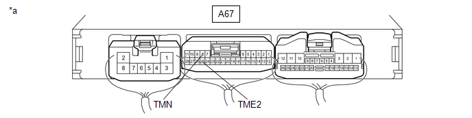
| *a | Component with harness connected (Engine Stop and Start ECU) | - | - |
Standard Voltage:
| Tester Connection | Condition | Specified Condition |
|---|---|---|
| A67-8 (TMN) - A67-25 (TME2) | Ignition switch ON, shift lever in neutral | 2.7 to 4.3 V |
| A67-8 (TMN) - A67-25 (TME2) | Ignition switch ON, shift lever in any position other than neutral | 0.7 to 1.9 V |
| OK |
 | REPLACE ENGINE STOP AND START ECU |
| NG |
 | REPLACE NEUTRAL POSITION SWITCH |
 Clutch Pedal Switch "A" Circuit Short to Ground (P083011)
DESCRIPTION HINT: This DTC is applicable to Manual Transaxle models only. The clutch stroke sensor assembly (for detecting pedal depression amount) and clutch switch assembly (for detecting the pedal depression endpoint) are installed to the clutch pedal...
 Starter Exceed Limited Number (P154563)
DESCRIPTION When the number of starter operations reaches the maximum number, the engine stop and start ECU stores DTC P154563 and blinks the stop and start cancel indicator...
Other information:
Toyota Yaris XP210 (2020-2026) Reapir and Service Manual: Freeze Frame Data
FREEZE FRAME DATA DESCRIPTION The engine stop and start ECU records vehicle and driving condition information as freeze frame data the moment a DTC is stored. When troubleshooting, freeze frame data can be helpful in determining whether the vehicle was moving or stationary, whether the engine was warmed up or not, as well as other data recorded at the time of a malfunction...
Toyota Yaris XP210 (2020-2026) Reapir and Service Manual: Back-up Light Assembly
ComponentsCOMPONENTS ILLUSTRATION *1 BACK-UP LIGHT ASSEMBLY *2 BACK-UP LIGHT LED *3 REAR FOG LIGHT LED *4 BACK-UP LIGHT LENS AND BODY RemovalREMOVAL PROCEDURE 1. REMOVE BACK-UP LIGHT ASSEMBLY (a) Disengage the clamps and disconnect the 2 connectors...
Categories
- Manuals Home
- Toyota Yaris Owners Manual
- Toyota Yaris Service Manual
- Fuse Panel Description
- Opening and Closing the Liftgate/Trunk Lid
- To Set Speed
- New on site
- Most important about car
Fuel Gauge
The fuel gauge shows approximately how much fuel is remaining in the tank when the ignition is switched ON. We recommend keeping the tank over 1/4 full.
