Toyota Yaris: Sfi System / Ignition Circuit
DESCRIPTION
A direct ignition system is used on this vehicle. The direct ignition system is a 1 cylinder ignition system which ignites one cylinder with one ignition coil. In the 1 cylinder ignition system, one spark plug is connected to the end of the secondary winding. High voltage is generated in the secondary winding and is applied directly to the spark plug. The spark of the spark plug passes from the center electrode to the ground electrode.
The ECM determines the ignition timing and transmits the ignition signals for each cylinder. Using the ignition signal, the ECM turns on and off the power transistor inside the igniter, which switches on and off a current to the primary coil. When the current to the primary coil is cut off, high voltage is generated in the secondary coil and this voltage is applied to the spark plugs to create sparks inside the cylinders.
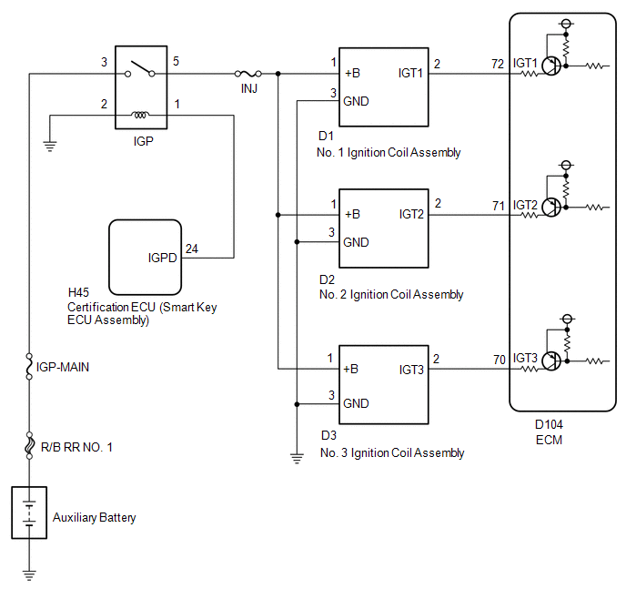
WIRING DIAGRAM
CAUTION / NOTICE / HINT
NOTICE:
Inspect the fuses for circuits related to this system before performing the following procedure.
HINT:
Perform a spark test first. If none of the cylinders spark, or if only some cylinders do not spark, check this circuit to determine if the ignition coil and spark plug are normal.
Click here

PROCEDURE
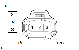
| 1. | CHECK TERMINAL VOLTAGE (POWER SOURCE OF IGNITION COIL ASSEMBLY) |
(a) Disconnect the ignition coil assembly connectors.
(b) Turn the ignition switch to ON.
| (c) Measure the voltage according to the value(s) in the table below. Standard Voltage:
|
|
| NG |
 | GO TO STEP 3 |
|

| 2. | CHECK HARNESS AND CONNECTOR (IGNITION COIL ASSEMBLY - ECM) |
(a) Disconnect the ignition coil assembly connectors.
(b) Disconnect the ECM connector.
(c) Measure the resistance according to the value(s) in the table below.
Standard Resistance:
| Tester Connection | Condition | Specified Condition |
|---|---|---|
| D1-2 (IGT1) - D104-72 (IGT1) | Always | Below 1 Ω |
| D2-2 (IGT2) - D104-71 (IGT2) | Always | Below 1 Ω |
| D3-2 (IGT3) - D104-70 (IGT3) | Always | Below 1 Ω |
| D1-2 (IGT1) or D104-72 (IGT1) - Body ground and other terminals | Always | 10 kΩ or higher |
| D2-2 (IGT2) or D104-71 (IGT2) - Body ground and other terminals | Always | 10 kΩ or higher |
| D3-2 (IGT3) or D107-70 (IGT3) - Body ground and other terminals | Always | 10 kΩ or higher |
| OK |
 | REPLACE ECM |
| NG |
 | REPAIR OR REPLACE HARNESS OR CONNECTOR |
| 3. | CHECK HARNESS AND CONNECTOR (IGNITION COIL ASSEMBLY - BODY GROUND) |
(a) Disconnect the ignition coil assembly connectors.
(b) Measure the resistance according to the value(s) in the table below.
Standard Resistance:
| Tester Connection | Condition | Specified Condition |
|---|---|---|
| D1-3 (GND) - Body ground | Always | Below 1 Ω |
| D2-3 (GND) - Body ground | Always | Below 1 Ω |
| D3-3 (GND) - Body ground | Always | Below 1 Ω |
| NG |
 | REPAIR OR REPLACE HARNESS OR CONNECTOR |
|

| 4. | CHECK HARNESS AND CONNECTOR (IGP RELAY - IGNITION COIL ASSEMBLY) |
(a) Remove the IGP relay from No. 1 engine room relay block assembly.
(b) Disconnect the ignition coil assembly connectors.
(c) Measure the resistance according to the value(s) in the table below.
Standard Resistance:
| Tester Connection | Condition | Specified Condition |
|---|---|---|
| 5 (IGP relay) - D1-1 (+B) | Always | Below 1 Ω |
| 5 (IGP relay) - D2-1 (+B) | Always | Below 1 Ω |
| 5 (IGP relay) - D3-1 (+B) | Always | Below 1 Ω |
| 5 (IGP relay) or D1-1 (+B) - Body ground and other terminals | Always | 10 kΩ or higher |
| 5 (IGP relay) or D2-1 (+B) - Body ground and other terminals | Always | 10 kΩ or higher |
| 5 (IGP relay) or D3-1 (+B) - Body ground and other terminals | Always | 10 kΩ or higher |
| OK |
 | GO TO ECM POWER SOURCE CIRCUIT |
| NG |
 | REPAIR OR REPLACE HARNESS OR CONNECTOR |
 MIL Circuit
DESCRIPTION The Malfunction Indicator Lamp (MIL) is used to indicate vehicle malfunctions detected by the ECM. The MIL operation can be checked visually...
 Rough Idling
DESCRIPTION Problem Symptom Suspected Area Trouble Area
Engine speed fluctuation due to abnormal combustion
Idle speed too low or high
Strong engine vibration due to above symptoms
Ignition malfunction
Deviation in air fuel ratio (Excessive or insufficient intake air volume or fuel supply)
Insufficient compression
Changes in load from another system
Ignition system
Spark plug
Ignition coil assembly
Fuel system
Direct fuel injector assembly
Port fuel injector assembly
Fuel pump assembly (for high pressure side)
Fuel pump (for low pressure side)
Fuel pump control circuit
Fuel line
Purge VSV system
Fuel quality (existence of foreign matter, degradation)
Intake and exhaust systems
Mass air flow meter sub-assembly
Intake system
(Air leaks or deposit accumulation)
Throttle body with motor assembly
Air fuel ratio sensor (sensor 1)
Air fuel ratio sensor (sensor 2)
Cam timing oil control solenoid assembly
Variable Valve Timing system (VVT system)
Other control systems
ECM
Wire harness or connector
Knock control sensor
Engine coolant temperature sensor
Engine
Water control valve
Engine assembly
Engine mount
High load from another system
Air conditioning system
Power steering system
Electrical load signal system
SYMPTOM AND CAUSE OF SYSTEM MALFUNCTION HINT: The following are descriptions of the characteristics of each system malfunction...
Other information:
Toyota Yaris XP210 (2020-2026) Owner's Manual: Hazardous Driving
When driving on ice or in water, snow, mud, sand, or similar hazards: Be cautious and allow extra distance for braking. Avoid sudden braking and sudden maneuvering. Do not pump the brakes. Continue to press down on the brake pedal. Refer to Antilock Brake System (ABS)...
Toyota Yaris XP210 (2020-2026) Reapir and Service Manual: Removal
REMOVAL CAUTION / NOTICE / HINT NOTICE: After replacing the front disc brake pads, the brake pedal may feel soft due to clearance between the front disc brake pads and front disc. Depress the brake pedal several times until the brake pedal feels firm...
Categories
- Manuals Home
- Toyota Yaris Owners Manual
- Toyota Yaris Service Manual
- Power Integration No.1 System Missing Message (B235287,B235587,B235787-B235987)
- Battery Monitor Module General Electrical Failure (P058A01)
- Opening and Closing the Liftgate/Trunk Lid
- New on site
- Most important about car
Keys

To use the auxiliary key, press the knob and pull out the auxiliary key from the smart key.
