Toyota Yaris: Power Mirror Control System / Terminals Of Ecu
TERMINALS OF ECU
CHECK MAIN BODY ECU (MULTIPLEX NETWORK BODY ECU) AND POWER DISTRIBUTION BOX ASSEMBLY
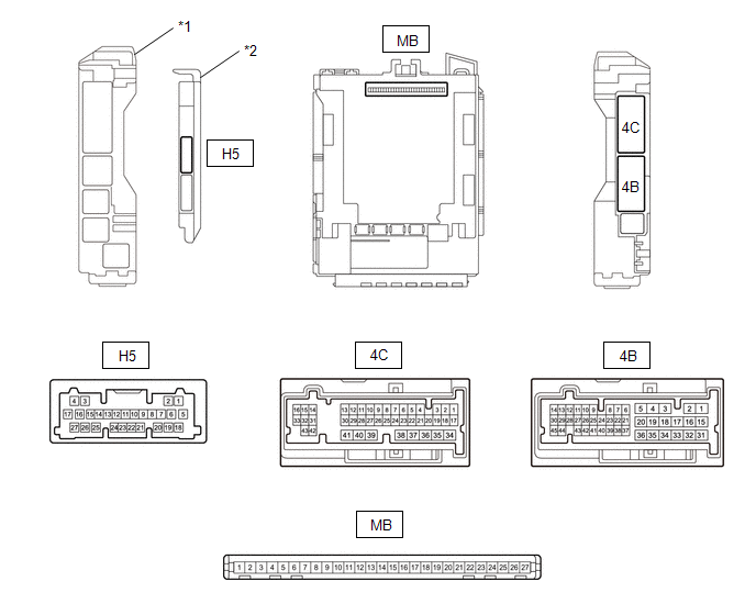
| *1 | Power Distribution Box Assembly | *2 | Main Body ECU (Multiplex Network Body ECU) |
(a) Remove the main body ECU (multiplex network body ECU) from the power distribution box assembly.
Click here
.gif)
(b) Reconnect the power distribution box assembly connectors.
(c) Measure the resistance and voltage according to the value(s) in the table below.
| Terminal No. (Symbol) | Terminal Description | Condition | Specified Condition |
|---|---|---|---|
| MB-26 (BECU) - Body ground | Auxiliary battery power supply | Ignition switch off | 11 to 14 V |
| MB-27 (IGR) - Body ground | Ignition power supply (IG signal) | Ignition switch off | Below 1 V |
| Ignition switch ON | 11 to 14 V | ||
| MB-13 (GND1) - Body ground | Body Ground | Always | Below 1 Ω |
(d) Install the main body ECU (multiplex network body ECU) to power distribution box assembly.
Click here
(e) Measure the voltage according to the value(s) in the table below.
| Terminal No. (Symbol) | Terminal Description | Condition | Specified Condition |
|---|---|---|---|
| H5-26 (AMR) - Body ground | Power retract mirror motor drive voltage (Input) | Auto retractable outer mirror switch on outer mirror switch assembly auto retracted position. | Below 1 V |
| Auto retractable outer mirror switch on outer mirror switch assembly return position. | 11 to 14 V | ||
| H5-27 (RET) - Body ground | Power retract mirror motor drive voltage (Input) | Auto retractable outer mirror switch on outer mirror switch assembly retracted position. | Below 1 V |
| Auto retractable outer mirror switch on outer mirror switch assembly driving position. | 11 to 14 V | ||
| 4B-2 - Body ground | Mirror heater drive voltage (Output) | Ignition switch ON, rear defogger switch off. | Below 1 V |
| Ignition switch ON, rear defogger switch on. | 11 to 14 V | ||
| 4C-10 - Body ground | Power retract mirror motor drive voltage (Output) | Outer rear view mirror assembly moves to the retracted position. | Below 1 V |
| Outer rear view mirror assembly not move. | 11 to 14 V | ||
| 4C-21 - Body ground | Power retract mirror motor drive voltage (Output) | Outer rear view mirror assembly moves to the return position. | Below 1 V |
| Outer rear view mirror assembly not move. | 11 to 14 V |
CHECK AIR CONDITIONING AMPLIFIER ASSEMBLY
Click here
AIR CONDITIONING CONTROL ASSEMBLY
Click here
 Diagnosis System
DIAGNOSIS SYSTEM CHECK DLC3 (a) Check the DLC3. Click here
INSPECT AUXILIARY BATTERY VOLTAGE (a) Measure the auxiliary battery voltage with the ignition switch off...
 Data List / Active Test
DATA LIST / ACTIVE TEST DATA LIST NOTICE: In the table below, the values listed under "Normal Condition" are reference values. Do not depend solely on these reference values when deciding whether a part is faulty or not...
Other information:
Toyota Yaris XP210 (2020-2026) Reapir and Service Manual: Turn Signal Light Circuit Current Below Threshold (B150718)
DESCRIPTION This DTC is stored when the combination meter assembly detects an open in a front turn signal light circuit or rear turn signal light circuit. HINT: If there is an open in a front turn signal light circuit or rear turn signal light circuit, the turn signal lights on the side with the open circuit will blink faster than usual...
Toyota Yaris XP210 (2020-2026) Reapir and Service Manual: Components
COMPONENTS ILLUSTRATION *1 FUEL PUMP *2 FUEL SUCTION WITH PUMP AND GAUGE TUBE ASSEMBLY *3 FUEL SENDER GAUGE ASSEMBLY *4 CANISTER (FUEL SUCTION WITH PUMP AND GAUGE TUBE ASSEMBLY) *5 FUEL MAIN VALVE ASSEMBLY *6 NO. 3 FUEL SUCTION SUPPORT *7 WIRE HARNESS *8 SPACER *9 O-RING *10 SUB-ASSEMBLY SUPPORT *11 NO...
Categories
- Manuals Home
- Toyota Yaris Owners Manual
- Toyota Yaris Service Manual
- Fuse Panel Description
- Maintenance
- Removal
- New on site
- Most important about car
Key Suspend Function
If a key is left in the vehicle, the functions of the key left in the vehicle are temporarily suspended to prevent theft of the vehicle.
To restore the functions, press the unlock button on the functions-suspended key in the vehicle.