Toyota Yaris: Stop And Start System / Terminals Of Ecu
TERMINALS OF ECU
ENGINE STOP AND START ECU
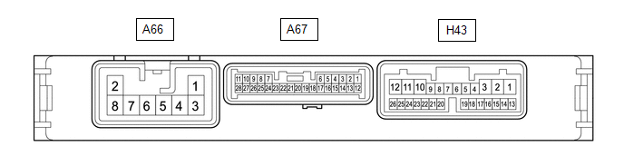
(a) Disconnect the engine stop and start ECU connectors.
(b) Measure the resistance and voltage according to the value(s) in the table below.
| Terminal No. (Symbol) | Terminal Description | Condition | Specified Condition |
|---|---|---|---|
| A66-1 (BIN2) - Body ground | Auxiliary battery | Always | 9.5 to 14 V |
| A66-2 (GND2) - Body ground | Ground | Always | Below 1 Ω |
| A66-3 (BIN1) - Body ground | Auxiliary battery | Always | 9.5 to 14 V |
| A66-8 (GND1) - Body ground | Ground | Always | Below 1 Ω |
| A67-1 (+B) - Body ground | Power source of engine stop and start ECU | Ignition switch ON | 9.5 to 14 V |
| A67-6 (DGND) - Body ground | Ground | Always | Below 1 Ω |
| A67-10 (NE) - Body ground | Engine speed signal from ECM | Always | Pulse generation (see waveform 1) |
| H43-13 (CANH) - Body ground | CAN communication | Always | 200 Ω or higher |
| H43-14 (CANL) - Body ground | CAN communication | Always | 200 Ω or higher |
| H43-15 (LC1H) - Body round | Local bus communication line | Always | 200 Ω or higher |
| H43-16 (LC1L) - Body round | Local bus communication line | Always | 200 Ω or higher |
| H43-18 (IGP) - Body ground | Ignition switch signal | Ignition switch ON | 9.5 to 14 V |
| H43-19 (ACC) - Body ground | Ignition switch signal | Ignition switch ACC | 9.5 to 14 V |
| H43-21 (IGR) - Body ground | Ignition switch signal | Ignition switch ON | 9.5 to 14 V |
(c) Reconnect the engine stop and start ECU connectors.
(d) Measure the resistance, voltage and pulse according to the value(s) in the table below.
| Terminal No. (Symbol) | Terminal Description | Condition | Specified Condition |
|---|---|---|---|
| A67-3 (BRE2) - Body ground | Ground (vacuum sensor assembly) | Always | Below 1 Ω |
| A67-7 (BNT1) - A67-6 (DGND) | Engine hood courtesy switch (hood lock assembly) signal |
| Below 1.5 V |
| 8 to 14 V | ||
| A67-8 (TMN) - A67-25 (TME2) | Neutral position switch signal |
| 2.7 to 4.3 V |
| 0.7 to 1.9 V | ||
| A67-10 (NE) - A67-6 (DGND) | Engine speed signal from ECM | Idling after engine warmed up | Pulse generation (See waveform 1) |
| A67-13 (PB) - A67-3 (BRE2) | Vacuum sensor assembly signal |
| 1.6 to 2.0 V |
| 2.2 to 2.6 V | ||
| 3.4 to 3.8 V | ||
| A67-14 (BRVC) - A67-6 (DGND) | Vacuum sensor assembly power supply |
| 4.5 to 5.5 V |
| A67-17 (CLL) - A67-6 (DGND) | Clutch switch assembly signal |
| 8 to 14 V |
| Below 1.5 V | ||
| A67-19 (DON2) - A67-6 (DGND) | External backup boost converter (eco run vehicle converter assembly) signal | Engine running | Pulse generation (See waveform 2) |
| A67-21 (STA) - A67-6 (DGND) | Starter pinion operation signal | Cranking | 6.0 V or more |
| A67-26 (TMVC) - A67-6 (DGND) | Neutral position switch power supply |
| 4.5 to 5.5 V |
| H43-23 (IG31) - A67-6 (DGND) | Backup boost converter signal | Ignition switch ON | 10.5 to 16 V |
| H43-3 (IG41) - A67-6 (DGND) | Backup boost converter signal | Ignition switch ON | 10.5 to 16 V |
| H43-5 (ECAN) - A67-6 (DGND) | Stop and start system cancel switch (combination switch assembly) signal |
| Below 1.5 V |
| 8 to 14 V | ||
| H43-10 (IG12) - A67-6 (DGND) | Backup boost converter signal | Ignition switch ON | 10.5 to 16 V |
| H43-11 (B43) - A67-6 (DGND) | Backup boost converter signal | Always | 10.5 to 16 V |
| H43-18 (IGP) - A67-6 (DGND) | Ignition switch signal | Ignition switch ACC | Below 1 V |
| Ignition switch ON | 9.5 to 14 V | ||
| H43-19 (ACC) - A67-6 (DGND) | Ignition switch signal | Ignition switch off | Below 1 V |
| Ignition switch ACC | 9.5 to 14 V | ||
| H43-21 (IGR) - A67-6 (DGND) | Ignition switch signal | Ignition switch ACC | Below 1 V |
| Ignition switch ON | 9.5 to 14 V | ||
| H43-23 (IG31) - A67-6 (DGND) | Backup boost converter signal | Ignition switch ON | 10.5 to 16 V |
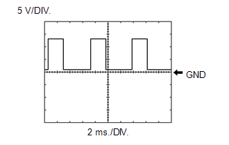
(e) Waveform 1
| Item | Content |
|---|---|
| Tester Connection | A67-10 (NE) - A67-6 (DGND) |
| Tool Setting | 5 V/DIV., 2 ms./DIV. |
| Condition | Idling after engine warmed up |
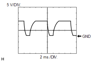
(f) Waveform 2
| Item | Content |
|---|---|
| Tester Connection | A67-19 (DON2) - A67-6 (DGND) |
| Tool Setting | 5 V/DIV., 2 ms./DIV. |
| Condition | Engine running |
 Problem Symptoms Table
PROBLEM SYMPTOMS TABLE Stop and Start System Symptom Suspected Area Link Stop and start system does not operate Refer to "Stop and Start System does not Operate"
Refer to "Stop and Start System does not Operate (Battery Condition)"
Restarting after a short period of time from an idling stop Refer to "Restarting after a Short Period of Time from an Idling Stop"
After engine stops due to stop and start system, engine does not restart Refer to "After Engine Stops due to Stop and Start System, Engine does not Restart"
Failure to restart from IG-ON engine stall Refer to "Failure to Restart from IG-ON Engine Stall"
Stop and start cancel indicator does not operate Combination meter assembly
Indicator circuit (CAN communication system)
Engine stop and start ECU
Stop and start indicator does not operate Combination meter assembly
Indicator circuit (CAN communication system)
Engine stop and start ECU
Stop and start control cannot be canceled ECAN terminal voltage
Stop and start cancel switch circuit
Multi-information display screen does not change after pressing steering pad switch assembly...
 Diagnosis System
DIAGNOSIS SYSTEM DESCRIPTION When troubleshooting a vehicle with a diagnosis system, the only difference from the usual troubleshooting procedure is connecting the GTS to the vehicle and reading various data output from the engine stop and start ECU...
Other information:
Toyota Yaris XP210 (2020-2026) Reapir and Service Manual: General Information
GENERAL INFORMATION A large number of ECU controlled systems are used in this vehicle. In general, ECU controlled systems are considered to be very intricate, requiring a high level of technical knowledge to troubleshoot. However, most problem checking procedures only involve inspecting the ECU controlled system circuits one by one...
Toyota Yaris XP210 (2020-2026) Reapir and Service Manual: Installation
INSTALLATION PROCEDURE 1. INSTALL COMBINATION METER ASSEMBLY (a) Connect the 2 connectors. (b) Engage the guide and clips to install the combination meter assembly. (c) Install the 2 screws. 2. INSTALL INSTRUMENT CLUSTER FINISH PANEL ASSEMBLY Click here 3...
Categories
- Manuals Home
- Toyota Yaris Owners Manual
- Toyota Yaris Service Manual
- Key Battery Replacement
- Immobilizer System
- To Set Speed
- New on site
- Most important about car
Front Seat Belt Pretensioners
The front seat belt pretensioners are designed to deploy in moderate or severe frontal, near frontal collisions.
In addition, the pretensioners operate when a side collision or a rollover accident is detected. The pretensioners operate differently depending on what types of air bags are equipped. For more details about the seat belt pretensioner operation, refer to the SRS Air Bag Deployment Criteria.