Toyota Yaris: Power Mirror Control System / System Diagram
SYSTEM DIAGRAM
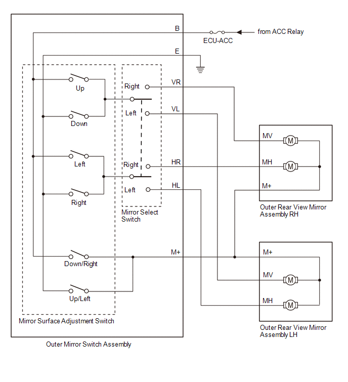
ELECTRICAL REMOTE CONTROL MIRROR FUNCTION
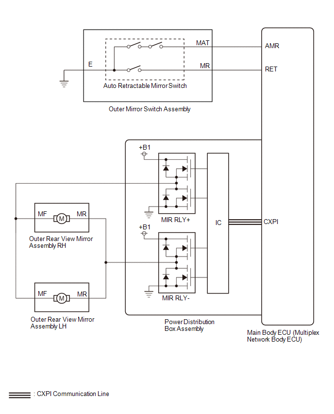
POWER RETRACT MIRROR FUNCTION
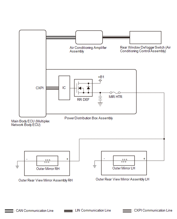
MIRROR HEATER FUNCTION

PARTS LOCATION ILLUSTRATION
*1 OUTER REAR VIEW MIRROR ASSEMBLY LH - OUTER MIRROR LH *2 OUTER REAR VIEW MIRROR ASSEMBLY RH - OUTER MIRROR RH *3 OUTER MIRROR SWITCH ASSEMBLY *4 NO...
SYSTEM DESCRIPTION POWER MIRROR CONTROL SYSTEM DESCRIPTION (a) This system has the following functions: electrical remote control mirror function, power retract mirror function, auto power retract mirror function and mirror heater function...
Other information:
TERMINALS OF ECU CHECK STEREO COMPONENT EQUALIZER ASSEMBLY
Terminal No. (Symbol) Terminal Description Condition Specified Condition O131-15(+B) - O131-30(GND) Power source Always 11 to 14 V O131-29(IGP) - O131-30(GND) Power source (IG) Ignition switch ON 11 to 14 V O131-14(ACC) - O131-30(GND) Power source (ACC) Ignition switch ACC 11 to 14 V O131-30(GND) - Body ground Ground Always Below 1 Ω O132-1(MC1+) - O131-30(GND) Active noise control microphone input signal Active noise control microphone LH tapped with finger Pulse generation O132-5(MC1-) - O131-30(GND) Active noise control microphone input signal Always Below 1 Ω O132-2(MC2+) - O131-30(GND) Active noise control microphone input signal Active noise control microphone RH tapped with finger Pulse generation O132-6(MC2-) - O131-30(GND) Active noise control microphone input signal Always Below 1 Ω O131-3(NEI) - O131-30(GND) Engine pulse signal Idling with warm engine Pulse generation (See waveform 1) O131-24(FLI-) Active noise control microphone output signal - - O131-9(FLI+) Active noise control microphone output signal - - O131-23(FRI-) Active noise control microphone output signal - - O131-8(FRI+) Active noise control microphone output signal - - O131-5(RRI+) Active noise control microphone output signal - - O131-20(RRI-) Active noise control microphone output signal - - O131-6(RLI+) Active noise control microphone output signal - - O131-21(RLI-) Active noise control microphone output signal - - O131-7(ASG1) Shield ground - - O131-22(ASG2) Shield ground - - O131-12(FR+) - O131-30(GND) Sound signal Active noise control system operating Pulse generation O131-27(FR-) - O131-30(GND) Sound signal Active noise control system operating Pulse generation O131-13(FL+) - O131-30(GND) Sound signal Active noise control system operating Pulse generation O131-28(FL-) - O131-30(GND) Sound signal Active noise control system operating Pulse generation O131-10(RR+) - O131-30(GND) Sound signal Active noise control system operating Pulse generation O131+25(RR-) - O131-30(GND) Sound signal Active noise control system operating Pulse generation O131-11(RL+) - O131-30(GND) Sound signal Active noise control system operating Pulse generation O131-28(RL-) - O131-30(GND) Sound signal Active noise control system operating Pulse generation O131-1(CANH) CAN communication signal - - O131-16(CANL) CAN communication signal - - (a) Waveform 1 HINT: The oscilloscope waveform shown in the illustration is an example for reference only...
DESCRIPTION The certification ECU (smart key ECU assembly) has a power source mode switching function. This DTC is stored when the IGE input (the steering lock motor activation permission signal) sent directly from the certification ECU (smart key ECU assembly) to the steering lock ECU (steering lock actuator or upper bracket assembly) is determined to be abnormal...
Categories
No special break-in is necessary, but a few precautions in the first 600
miles (1,000 km) may add to the performance, economy, and life of
the vehicle.
Do not race the engine.
Do not maintain one constant speed, either slow or fast, for a long
period of time.
Do not drive constantly at full-throttle or high engine rpm for
extended periods of time.
Avoid unnecessary hard stops.
Avoid full-throttle starts.
read more