Toyota Yaris: Smart Key System (for Entry Function) / Driver Side Door Entry Unlock Function does not Operate
DESCRIPTION
If the entry unlock function does not operate for the driver door only, but the entry lock function operates, the request code is being transmitted properly from the driver door. In this case, there may be a problem related to the unlock sensor (connection between the certification ECU (smart key ECU assembly) and front door outside handle assembly LH).
WIRING DIAGRAM
CAUTION / NOTICE / HINT
NOTICE:
- When using the GTS with the ignition switch off, connect the GTS to the DLC3 and turn a courtesy light switch on and off at intervals of 1.5 seconds or less until communication between the GTS and the vehicle begins. Then select the vehicle type under manual mode and enter the following menus: Body Electrical / Smart Key. While using the GTS, periodically turn a courtesy light switch on and off at intervals of 1.5 seconds or less to maintain communication between the GTS and the vehicle.
-
The smart key system (for Entry Function) uses the CAN communication system. Inspect the communication function by following How to Proceed with Troubleshooting. Troubleshoot the smart key system (for Entry Function) after confirming that the communication systems are functioning properly.
Click here

-
Before replacing the certification ECU (smart key ECU assembly), refer to Precaution.
Click here

- After repair, confirm that no DTCs are output.
- Check that there are no electrical key transmitter sub-assemblies in the vehicle.
PROCEDURE
| 1. | CHECK POWER DOOR LOCK CONTROL SYSTEM |
(a) When the door control switch on the multiplex network master switch assembly is operated, check that the doors unlock and lock according to the switch operation.
Click here

OK:
Door locks operate normally.
| NG |
 | GO TO POWER DOOR LOCK CONTROL SYSTEM |
|

| 2. | CHECK ENTRY OPERATION |
(a) Check that the entry unlock function.
| (1) Turn the ignition switch off. |
|

(2) Open and close the driver door.
(3) With the electrical key transmitter sub-assembly outside of the vehicle, press the lock switch of the electrical key transmitter sub-assembly to lock all of the doors.
(4) Hold the electrical key transmitter sub-assembly at the same height as the door outside handle assembly LH and approximately 0.3 m (0.984 ft.) from the driver door.
(5) Check that the LED of the electrical key transmitter sub-assembly blinks.
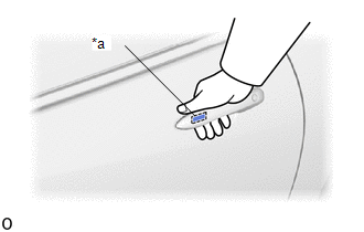
(6) Touch the unlock sensor on the backside of the front door outside handle assembly LH for 2 seconds or more.*
- *: Perform this step 3 seconds or more after performing step (3).
HINT:
When checking the operation of the unlock sensor again, make sure to perform the procedure from step (1).
| Result | Proceed to |
|---|---|
| Entry function does not operate normally | A |
| Entry function operates normally | B |
| B |
 | GO TO CHECK FOR INTERMITTENT PROBLEMS (OPERATION HISTORY) |
|

| 3. | READ VALUE USING GTS (FL DOOR LOCK POSITION SWITCH STATUS) |
(a) Read the Data List according to the display on the GTS.
Body Electrical > Main Body > Data List| Tester Display | Measurement Item | Range | Normal Condition | Diagnostic Note |
|---|---|---|---|---|
| FL Door Lock Position Switch Status | Front door LH unlock detection switch signal | Lock or Unlock | Lock: Front door LH locked Unlock: Front door LH unlocked | - |
| Tester Display |
|---|
| FL Door Lock Position Switch Status |
OK:
The GTS display changes correctly in response to the lock/unlock operation of the driver door.
| NG |
 | GO TO LIGHTING SYSTEM (Proceed to Door Unlock Detection Switch Circuit) |
|

| 4. | READ VALUE USING GTS (DRIVER SIDE UNLOCK SENSOR) |
| (a) Open and close the driver door. |
|
(b) With the electrical key transmitter sub-assembly outside of the vehicle, press the lock switch of the electrical key transmitter sub-assembly to lock all of the doors.
(c) Hold the electrical key transmitter sub-assembly at the same height as the door outside handle assembly LH and approximately 0.3 m (0.984 ft.) from the driver door.
(d) Check that the LED of the electrical key transmitter sub-assembly blinks.
(e) Read the Data List according to the display on the GTS.
(f) Touch the unlock sensor on the backside of the front door outside handle assembly LH for 2 seconds or more.*
- *: Perform this step 3 seconds or more after performing step (b).
HINT:
When checking the operation of the unlock sensor again, make sure to perform the procedure from step (a).
Body Electrical > Smart Key > Data List| Tester Display | Measurement Item | Range | Normal Condition | Diagnostic Note |
|---|---|---|---|---|
| Driver Side Unlock Sensor | Driver door touch sensor (unlock sensor) | OFF or ON | OFF: Driver door touch sensor (unlock sensor) not touched ON: Driver door touch sensor (unlock sensor) touched |
|
| Tester Display |
|---|
| Driver Side Unlock Sensor |
OK:
The GTS display changes correctly in response to the operation of the front door outside handle assembly LH.
| OK |
 | REPLACE CERTIFICATION ECU (SMART KEY ECU ASSEMBLY) |
|

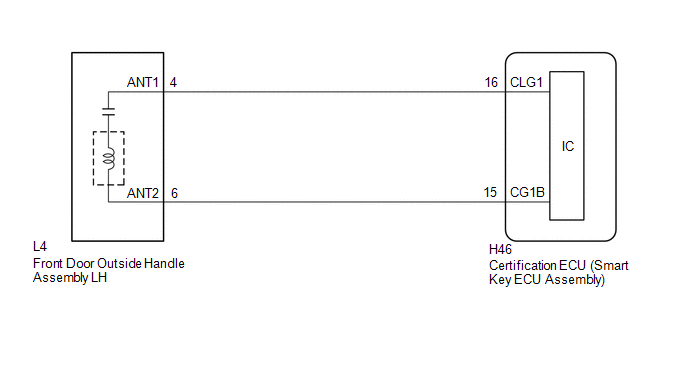
| 5. | CHECK HARNESS AND CONNECTOR (CERTIFICATION ECU (SMART KEY ECU ASSEMBLY) - FRONT DOOR OUTSIDE HANDLE ASSEMBLY LH) |
(a) Disconnect the H46 certification ECU (smart key ECU assembly) connector.
(b) Disconnect the L4 front door outside handle assembly LH connector.
(c) Measure the resistance according to the value(s) in the table below.
Standard Resistance:
| Tester Connection | Condition | Specified Condition |
|---|---|---|
| H46-16 (CLG1) - L4-4 (ANT1) | Always | Below 1 Ω |
| H46-15 (CG1B) - L4-6 (ANT2) | Always | Below 1 Ω |
| H46-16 (CLG1) or L4-4 (ANT1) - Other terminals and body ground | Always | 10 kΩ or higher |
| H46-15 (CG1B) or L4-6 (ANT2) - Other terminals and body ground | Always | 10 kΩ or higher |
(d) Reconnect the L4 front door outside handle assembly LH connector.
(e) Reconnect the H46 certification ECU (smart key ECU assembly) connector.
| NG |
 | REPAIR OR REPLACE HARNESS OR CONNECTOR |
|

| 6. | READ VALUE USING GTS (DRIVER SIDE UNLOCK SENSOR) |
| (a) Open and close the driver door. |
|

(b) With the electrical key transmitter sub-assembly outside of the vehicle, press the lock switch of the electrical key transmitter sub-assembly to lock all of the doors.
(c) Hold the electrical key transmitter sub-assembly at the same height as the door outside handle assembly LH and approximately 0.3 m (0.984 ft.) from the driver door.
(d) Check that the LED of the electrical key transmitter sub-assembly blinks.
(e) Read the Data List according to the display on the GTS.
(f) Touch the unlock sensor on the backside of the front door outside handle assembly LH for 2 seconds or more.*
- *: Perform this step 3 seconds or more after performing step (b).
HINT:
When checking the operation of the unlock sensor again, make sure to perform the procedure from step (a).
Body Electrical > Smart Key > Data List| Tester Display | Measurement Item | Range | Normal Condition | Diagnostic Note |
|---|---|---|---|---|
| Driver Side Unlock Sensor | Driver door touch sensor (unlock sensor) | OFF or ON | OFF: Driver door touch sensor (unlock sensor) not touched ON: Driver door touch sensor (unlock sensor) touched |
|
| Tester Display |
|---|
| Driver Side Unlock Sensor |
OK:
The GTS display changes correctly in response to the operation of the front door outside handle assembly LH.
| OK |
 | END (CONNECTOR WAS NOT CONNECTED SECURELY) |
| NG |
 | REPLACE FRONT DOOR OUTSIDE HANDLE ASSEMBLY LH |
 All Door Entry Lock/Unlock Functions do not Operate, but Wireless Functions Operate
DESCRIPTION When the wireless operation can be used to lock and unlock the doors, communication between the smart door control receiver assembly and certification ECU (smart key ECU assembly) is normal...
 Front Passenger Side Door Entry Unlock Function does not Operate
DESCRIPTION If the entry unlock function does not operate for the front passenger door only, but the entry lock function operates, the request code is being transmitted properly from the front passenger door...
Other information:
Toyota Yaris XP210 (2020-2026) Reapir and Service Manual: Brake System
PrecautionPRECAUTION NOTICE: This vehicle is equipped with an SRS (Supplemental Restraint System). Failure to carry out service operations in the correct sequence could cause the SRS to unexpectedly deploy during servicing. This may cause a serious accident...
Toyota Yaris XP210 (2020-2026) Reapir and Service Manual: Problem Symptoms Table
PROBLEM SYMPTOMS TABLE HINT: If a problem occurs in certain locations or at certain times of day, check for the possibility of wave interference. When the electrical key transmitter sub-assembly is brought near a smart door control receiver assembly (RF band), door outside handle assembly (LF band), indoor electrical key antenna (LF band) or any of the electrical key antennas (LF band), the possibility of wave interference decreases...
Categories
- Manuals Home
- Toyota Yaris Owners Manual
- Toyota Yaris Service Manual
- Fuse Panel Description
- Brake System Control Module "A" System Voltage System Voltage Low (C137BA2)
- How to connect USB port/Auxiliary jack
- New on site
- Most important about car
Turning the Engine Off
Stop the vehicle completely. Manual transaxle: Shift into neutral and set the parking brake.Automatic transaxle: Shift the selector lever to the P position and set the parking brake.
Press the push button start to turn off the engine. The ignition position is off.