Toyota Yaris: Smart Key System (for Entry Function) / Front Passenger Side Door Entry Unlock Function does not Operate
DESCRIPTION
If the entry unlock function does not operate for the front passenger door only, but the entry lock function operates, the request code is being transmitted properly from the front passenger door. In this case, there may be a problem related to the unlock sensor (connection between the certification ECU (smart key ECU assembly) and front door outside handle assembly RH).
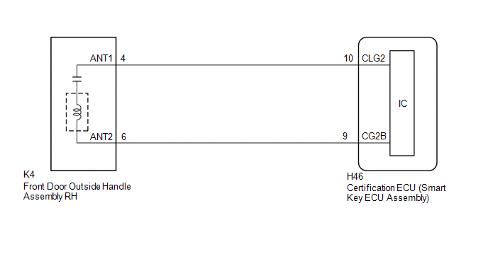
WIRING DIAGRAM
CAUTION / NOTICE / HINT
NOTICE:
- When using the GTS with the ignition switch off, connect the GTS to the DLC3 and turn a courtesy light switch on and off at intervals of 1.5 seconds or less until communication between the GTS and the vehicle begins. Then select the vehicle type under manual mode and enter the following menus: Body Electrical / Smart Key. While using the GTS, periodically turn a courtesy light switch on and off at intervals of 1.5 seconds or less to maintain communication between the GTS and the vehicle.
-
The smart key system (for Entry Function) uses the CAN communication system. Inspect the communication function by following How to Proceed with Troubleshooting. Troubleshoot the smart key system (for Entry Function) after confirming that the communication systems are functioning properly.
Click here

-
Before replacing the certification ECU (smart key ECU assembly), refer to Precaution.
Click here

- After repair, confirm that no DTCs are output.
- Check that there are no electrical key transmitter sub-assemblies in the vehicle.
PROCEDURE
| 1. | CHECK POWER DOOR LOCK CONTROL SYSTEM |
(a) When the door control switch on the multiplex network master switch assembly is operated, check that the doors unlock and lock according to the switch operation.
Click here

OK:
Door locks operate normally.
| NG |
 | GO TO POWER DOOR LOCK CONTROL SYSTEM |
|

| 2. | CHECK ENTRY OPERATION |
(a) Check that the entry unlock function.
| (1) Turn the ignition switch off. |
|
(2) Open and close the front passenger door.
(3) With the electrical key transmitter sub-assembly outside of the vehicle, press the lock switch of the electrical key transmitter sub-assembly to lock all of the doors.
(4) Hold the electrical key transmitter sub-assembly at the same height as the door outside handle assembly RH and approximately 0.3 m (0.984 ft.) from the front passenger door.
(5) Check that the LED of the electrical key transmitter sub-assembly blinks.
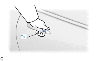
(6) Touch the unlock sensor on the backside of the front door outside handle assembly RH for 2 seconds or more.*
- *: Perform this step 3 seconds or more after performing step (3).
HINT:
When checking the operation of the unlock sensor again, make sure to perform the procedure from step (1).
| Result | Proceed to |
|---|---|
| Entry function does not operate normally | A |
| Entry function operates normally | B |
| B |
 | GO TO CHECK FOR INTERMITTENT PROBLEMS (OPERATION HISTORY) |
|

| 3. | READ VALUE USING GTS (FR DOOR LOCK POSITION SWITCH STATUS) |
(a) Read the Data List according to the display on the GTS.
Body Electrical > Main Body > Data List| Tester Display | Measurement Item | Range | Normal Condition | Diagnostic Note |
|---|---|---|---|---|
| FR Door Lock Position Switch Status | Front door RH unlock detection switch signal | Lock or Unlock | Lock: Front door RH locked Unlock: Front door RH unlocked | - |
| Tester Display |
|---|
| FR Door Lock Position Switch Status |
OK:
The GTS display changes correctly in response to the lock/unlock operation of the front passenger door.
| NG |
 | GO TO LIGHTING SYSTEM (Proceed to Door Unlock Detection Switch Circuit) |
|

| 4. | READ VALUE USING GTS (PASSENGER SIDE UNLOCK SENSOR) |
| (a) Open and close the front passenger door. |
|

(b) With the electrical key transmitter sub-assembly outside of the vehicle, press the lock switch of the electrical key transmitter sub-assembly to lock all of the doors.
(c) Hold the electrical key transmitter sub-assembly at the same height as the door outside handle assembly RH and approximately 0.3 m (0.984 ft.) from the front passenger door.
(d) Check that the LED of the electrical key transmitter sub-assembly blinks.
(e) Read the Data List according to the display on the GTS.
(f) Touch the unlock sensor on the backside of the front door outside handle assembly RH for 2 seconds or more.*
- *: Perform this step 3 seconds or more after performing step (b).
HINT:
When checking the operation of the unlock sensor again, make sure to perform the procedure from step (a).
Body Electrical > Smart Key > Data List| Tester Display | Measurement Item | Range | Normal Condition | Diagnostic Note |
|---|---|---|---|---|
| Passenger Side Unlock Sensor | Front passenger door touch sensor (unlock sensor) | OFF or ON | OFF: Front passenger door touch sensor (unlock sensor) not touched ON: Front passenger door touch sensor (unlock sensor) touched |
|
| Tester Display |
|---|
| Passenger Side Unlock Sensor |
OK:
The GTS display changes correctly in response to the operation of the front door outside handle assembly RH.
| OK |
 | REPLACE CERTIFICATION ECU (SMART KEY ECU ASSEMBLY) |
|

| 5. | CHECK HARNESS AND CONNECTOR (CERTIFICATION ECU (SMART KEY ECU ASSEMBLY) - FRONT DOOR OUTSIDE HANDLE ASSEMBLY RH) |
(a) Disconnect the H46 certification ECU (smart key ECU assembly) connector.
(b) Disconnect the K4 front door outside handle assembly RH connector.
(c) Measure the resistance according to the value(s) in the table below.
Standard Resistance:
| Tester Connection | Condition | Specified Condition |
|---|---|---|
| H46-10 (CLG2) - K4-4 (ANT1) | Always | Below 1 Ω |
| H46-9 (CG2B) - K4-6 (ANT2) | Always | Below 1 Ω |
| H46-10 (CLG2) or K4-4 (ANT1) - Other terminals and body ground | Always | 10 kΩ or higher |
| H46-9 (CG2B) or K4-6 (ANT2) - Other terminals and body ground | Always | 10 kΩ or higher |
(d) Reconnect the K4 front door outside handle assembly RH connector.
(e) Reconnect the H46 certification ECU (smart key ECU assembly) connector.
| NG |
 | REPAIR OR REPLACE HARNESS OR CONNECTOR |
|

| 6. | READ VALUE USING GTS (PASSENGER SIDE UNLOCK SENSOR) |
| (a) Open and close the front passenger door. |
|

(b) With the electrical key transmitter sub-assembly outside of the vehicle, press the lock switch of the electrical key transmitter sub-assembly to lock all of the doors.
(c) Hold the electrical key transmitter sub-assembly at the same height as the door outside handle assembly RH and approximately 0.3 m (0.984 ft.) from the front passenger door.
(d) Check that the LED of the electrical key transmitter sub-assembly blinks.
(e) Read the Data List according to the display on the GTS.
(f) Touch the unlock sensor on the backside of the front door outside handle assembly RH for 2 seconds or more.*
- *: Perform this step 3 seconds or more after performing step (b).
HINT:
When checking the operation of the unlock sensor again, make sure to perform the procedure from step (a).
Body Electrical > Smart Key > Data List| Tester Display | Measurement Item | Range | Normal Condition | Diagnostic Note |
|---|---|---|---|---|
| Passenger Side Unlock Sensor | Front passenger door touch sensor (unlock sensor) | OFF or ON | OFF: Front passenger door touch sensor (unlock sensor) not touched ON: Front passenger door touch sensor (unlock sensor) touched |
|
| Tester Display |
|---|
| Passenger Side Unlock Sensor |
OK:
The GTS display changes correctly in response to the operation of the front door outside handle assembly RH.
| OK |
 | END (CONNECTOR WAS NOT CONNECTED SECURELY) |
| NG |
 | REPLACE FRONT DOOR OUTSIDE HANDLE ASSEMBLY RH |
 Driver Side Door Entry Unlock Function does not Operate
DESCRIPTION If the entry unlock function does not operate for the driver door only, but the entry lock function operates, the request code is being transmitted properly from the driver door...
 Driver Side Door Entry Lock and Unlock Functions do not Operate
DESCRIPTION If the entry lock and unlock functions do not operate for the driver door only, the request code may not be being transmitted from the driver door or the front door outside handle assembly LH (touch sensor) may be malfunctioning...
Other information:
Toyota Yaris XP210 (2020-2026) Reapir and Service Manual: Parts Location
PARTS LOCATION ILLUSTRATION *A w/ Toyota Safety Sense - - *1 SIDE TURN SIGNAL LIGHT ASSEMBLY LH *2 SIDE TURN SIGNAL LIGHT ASSEMBLY RH *3 HEADLIGHT ASSEMBLY LH *4 HEADLIGHT ASSEMBLY RH *5 HEADLIGHT LENS SUB-ASSEMBLY LH *6 HEADLIGHT LENS SUB-ASSEMBLY RH *7 HEADLIGHT UNIT ASSEMBLY LH *8 HEADLIGHT UNIT ASSEMBLY RH *9 LIGHT CONTROL LED ECU LH *10 LIGHT CONTROL LED ECU RH *11 HEADLIGHT LEVELING MOTOR LH *12 HEADLIGHT LEVELING MOTOR RH *13 HEADLIGHT HOUSING SUB-ASSEMBLY LH (WIRE HARNESS LH) *14 HEADLIGHT HOUSING SUB-ASSEMBLY RH (WIRE HARNESS RH) *15 FOG LIGHT ASSEMBLY LH *16 FOG LIGHT ASSEMBLY RH *17 FORWARD RECOGNITION CAMERA *18 MILLIMETER WAVE RADAR SENSOR ASSEMBLY *19 ECM *20 POWER STEERING ECU ASSEMBLY *21 SKID CONTROL ECU (BRAKE ACTUATOR ASSEMBLY) *22 NO...
Toyota Yaris XP210 (2020-2026) Reapir and Service Manual: Inspection
INSPECTION CAUTION / NOTICE / HINT NOTICE: Do not apply positive (+) auxiliary battery voltage to any terminals, except terminal K7-2 (B) or L7-2 (B), to avoid damaging the pulse sensor inside the motor. Perform initialization of the power window system after removing, inspecting or replacing the power window regulator motor assembly...
Categories
- Manuals Home
- Toyota Yaris Owners Manual
- Toyota Yaris Service Manual
- Brake System Control Module "A" System Voltage System Voltage Low (C137BA2)
- Key Battery Replacement
- Removal
- New on site
- Most important about car
Front Seat Belt Pretensioners
The front seat belt pretensioners are designed to deploy in moderate or severe frontal, near frontal collisions.
In addition, the pretensioners operate when a side collision or a rollover accident is detected. The pretensioners operate differently depending on what types of air bags are equipped. For more details about the seat belt pretensioner operation, refer to the SRS Air Bag Deployment Criteria.