Toyota Yaris: Smart Key System (for Entry Function) / Driver Side Door Entry Lock and Unlock Functions do not Operate
DESCRIPTION
If the entry lock and unlock functions do not operate for the driver door only, the request code may not be being transmitted from the driver door or the front door outside handle assembly LH (touch sensor) may be malfunctioning. If the entry functions for other doors operate properly, communication between the electrical key transmitter sub-assembly and the smart door control receiver assembly is normal. In this case, there may be a problem with request code transmission (communication between the certification ECU (smart key ECU assembly) and front door outside handle assembly LH (electrical key antenna)), or there may be wave interference.
WIRING DIAGRAM

CAUTION / NOTICE / HINT
NOTICE:
- When using the GTS with the ignition switch off, connect the GTS to the DLC3 and turn a courtesy light switch on and off at intervals of 1.5 seconds or less until communication between the GTS and the vehicle begins. Then select the vehicle type under manual mode and enter the following menus: Body Electrical / Smart Key. While using the GTS, periodically turn a courtesy light switch on and off at intervals of 1.5 seconds or less to maintain communication between the GTS and the vehicle.
-
The smart key system (for Entry Function) uses the CAN communication system. Inspect the communication function by following How to Proceed with Troubleshooting. Troubleshoot the smart key system (for Entry Function) after confirming that the communication systems are functioning properly.
Click here

-
Before replacing the certification ECU (smart key ECU assembly), refer to Precaution.
Click here

- After repair, confirm that no DTCs are output.
- Check that there are no electrical key transmitter sub-assemblies in the vehicle.
HINT:
- If the driver door entry lock and unlock functions do not operate, the cause of the malfunction may be stored in the certification ECU (smart key ECU assembly).
- If the cause of the malfunction is stored in the certification ECU (smart key ECU assembly), the following table is helpful in checking whether the malfunction was caused by wave interference.
| Tester Display |
|---|
| Vehicle Control History (RoB) |
PROCEDURE
| 1. | CHECK POWER DOOR LOCK CONTROL SYSTEM |
(a) When the door control switch on the multiplex network master switch assembly is operated, check that the doors unlock and lock according to the switch operation.
Click here

OK:
Door locks operate normally.
| NG |
 | GO TO POWER DOOR LOCK CONTROL SYSTEM |
|

| 2. | CHECK ENTRY OPERATION |
(a) Check the operation of the entry lock and unlock functions.
| (1) Check that the entry unlock function.
HINT: When checking the operation of the unlock sensor again, make sure to perform the procedure from step (1). |
|

| (2) Check that the entry lock function.
|
|
| Result | Proceed to |
|---|---|
| Entry function does not operate normally | A |
| Entry function operates normally | B |
| B |
 | GO TO CHECK FOR INTERMITTENT PROBLEMS (OPERATION HISTORY) |
|

| 3. | CHECK WAVE ENVIRONMENT |
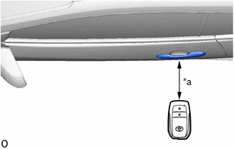
| (a) Bring the electrical key transmitter sub-assembly approximately 0.3 m (0.984 ft.) from the front door outside handle assembly LH and perform an entry function check. Click here
|
|


| Result | Proceed to |
|---|---|
| Entry function does not operate normally | A |
| Entry function operates normally | B |
| B |
 | AFFECTED BY WAVE INTERFERENCE |
|

| 4. | READ VALUE USING GTS (DRIVER SIDE UNLOCK SENSOR) |
| (a) Open and close the driver door. |
|
(b) With the electrical key transmitter sub-assembly outside of the vehicle, press the lock switch of the electrical key transmitter sub-assembly to lock all of the doors.
(c) Hold the electrical key transmitter sub-assembly at the same height as the door outside handle assembly LH and approximately 0.3 m (0.984 ft.) from the driver door.
(d) Check that the LED of the electrical key transmitter sub-assembly blinks.
(e) Read the Data List according to the display on the GTS.
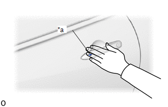
(f) Touch the unlock sensor on the backside of the front door outside handle assembly LH for 2 seconds or more.*
- *: Perform this step 3 seconds or more after performing step (b).
HINT:
When checking the operation of the unlock sensor again, make sure to perform the procedure from step (a).
Body Electrical > Smart Key > Data List| Tester Display | Measurement Item | Range | Normal Condition | Diagnostic Note |
|---|---|---|---|---|
| Driver Side Unlock Sensor | Driver door touch sensor (unlock sensor) | OFF or ON | OFF: Driver door touch sensor (unlock sensor) not touched ON: Driver door touch sensor (unlock sensor) touched |
|
| Tester Display |
|---|
| Driver Side Unlock Sensor |
OK:
The GTS display changes correctly in response to the operation of the front door outside handle assembly LH.
| NG |
 | GO TO STEP 6 |
|

| 5. | READ VALUE USING GTS (DRIVER SIDE LOCK SENSOR) |
| (a) Open and close the driver door. |
|

(b) Hold the electrical key transmitter sub-assembly at the same height as the door outside handle assembly LH and approximately 0.3 m (0.984 ft.) from the driver door.
(c) Read the Data List according to the display on the GTS.
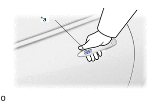
(d) Touch the lock sensor of the front door outside handle assembly LH (groove on the front door outside handle) with 2 or more fingers for 2 seconds or more.
HINT:
- If the door does not lock even when touching the lock sensor for 2 seconds or more, touch it with your palm.
- When checking the operation of the lock sensor again, make sure to perform the procedure from step (a).
- When checking the operation of the entry lock function several times, it can be operated up to 2 times consecutively. To operate the function 3 times or more consecutively, the doors need to be unlocked once. However, this is only for the entry lock function, other door lock operations, such as a wireless door lock operation can be performed consecutively.
| Tester Display | Measurement Item | Range | Normal Condition | Diagnostic Note |
|---|---|---|---|---|
| Driver Side Lock Sensor | Driver door touch sensor (lock sensor) | OFF or ON | OFF: Driver door touch sensor (lock sensor) not touched ON: Driver door touch sensor (lock sensor) touched |
|
| Tester Display |
|---|
| Driver Side Lock Sensor |
| Result | Proceed to |
|---|---|
| The GTS display does not change correctly in response to the operation of the front door outside handle assembly LH. | A |
| The GTS display changes correctly in response to the operation of the front door outside handle assembly LH. | B |
| B |
 | GO TO STEP 10 |
|

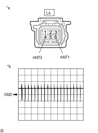
| 6. | CHECK HARNESS AND CONNECTOR (CERTIFICATION ECU (SMART KEY ECU ASSEMBLY) - FRONT DOOR OUTSIDE HANDLE ASSEMBLY LH) |
(a) Disconnect the H46 certification ECU (smart key ECU assembly) connector.
(b) Disconnect the L4 front door outside handle assembly LH connector.
(c) Measure the resistance according to the value(s) in the table below.
Standard Resistance:
| Tester Connection | Condition | Specified Condition |
|---|---|---|
| H46-16 (CLG1) - L4-4 (ANT1) | Always | Below 1 Ω |
| H46-15 (CG1B) - L4-6 (ANT2) | Always | Below 1 Ω |
| H46-16 (CLG1) or L4-4 (ANT1) - Other terminals and body ground | Always | 10 kΩ or higher |
| H46-15 (CG1B) or L4-6 (ANT2) - Other terminals and body ground | Always | 10 kΩ or higher |
(d) Reconnect the H46 certification ECU (smart key ECU assembly) connector.
| NG |
 | REPAIR OR REPLACE HARNESS OR CONNECTOR |
|

| 7. | CHECK CERTIFICATION ECU (SMART KEY ECU ASSEMBLY) (OUTPUT TO DRIVER DOOR ELECTRICAL KEY ANTENNA) |
| (a) Using an oscilloscope, check the waveform. OK:
*: For details about the entry function detection area, refer to Operation Check. Click here
|
|


| NG |
 | REPLACE CERTIFICATION ECU (SMART KEY ECU ASSEMBLY) |
|

| 8. | REPLACE FRONT DOOR OUTSIDE HANDLE ASSEMBLY LH |
(a) Replace the front door outside handle assembly LH with a new one or the front door outside handle assembly RH if it is functioning properly.
Click here

|

| 9. | CHECK ENTRY OPERATION |
(a) Check that the function operates normally.
Click here

| Result | Proceed to |
|---|---|
| Entry function operates normally | A |
| Entry function does not operate normally | B |
| A |
 | END (FRONT DOOR OUTSIDE HANDLE ASSEMBLY LH WAS DEFECTIVE) |
| B |
 | REPLACE CERTIFICATION ECU (SMART KEY ECU ASSEMBLY) |
| 10. | CHECK KEY DIAGNOSTIC MODE |
(a) Check the following antenna in key diagnostic mode.
Body Electrical > Smart Key > Utility| Tester Display |
|---|
| Communication Check(Key Diag Mode) |
(b) Select either channel 1 or channel 2 and perform key diagnostic mode inspection for each channel.
| (1) Check the electrical key antenna (for driver door): When the electrical key transmitter sub-assembly is brought within 0.7 to 1 m (2.30 to 3.28 ft.) of the front door outside handle assembly LH, check that the wireless buzzer sounds. HINT:
|
|
| Result | Proceed to |
|---|---|
| Wireless buzzer does not sound | A |
| Wireless buzzer sounds | B |
| B |
 | REPLACE CERTIFICATION ECU (SMART KEY ECU ASSEMBLY) |
|

| 11. | CHECK HARNESS AND CONNECTOR (CERTIFICATION ECU (SMART KEY ECU ASSEMBLY) - FRONT DOOR OUTSIDE HANDLE ASSEMBLY LH) |
(a) Disconnect the H46 certification ECU (smart key ECU assembly) connector.
(b) Disconnect the L4 front door outside handle assembly LH connector.
(c) Measure the resistance according to the value(s) in the table below.
Standard Resistance:
| Tester Connection | Condition | Specified Condition |
|---|---|---|
| H46-16 (CLG1) - L4-4 (ANT1) | Always | Below 1 Ω |
| H46-15 (CG1B) - L4-6 (ANT2) | Always | Below 1 Ω |
| H46-16 (CLG1) or L4-4 (ANT1) - Other terminals and body ground | Always | 10 kΩ or higher |
| H46-15 (CG1B) or L4-6 (ANT2) - Other terminals and body ground | Always | 10 kΩ or higher |
(d) Reconnect the H46 certification ECU (smart key ECU assembly) connector.
| NG |
 | REPAIR OR REPLACE HARNESS OR CONNECTOR |
|

| 12. | CHECK CERTIFICATION ECU (SMART KEY ECU ASSEMBLY) (OUTPUT TO DRIVER DOOR ELECTRICAL KEY ANTENNA) |
| (a) Using an oscilloscope, check the waveform. OK:
*: For details about the entry function detection area, refer to Operation Check. Click here
|
|

| NG |
 | REPLACE CERTIFICATION ECU (SMART KEY ECU ASSEMBLY) |
|

| 13. | CHECK ENTRY OPERATION |
(a) Connect all connectors and check that the function operates normally.
Click here

| Result | Proceed to |
|---|---|
| Entry function does not operate normally | A |
| Entry function operates normally | B |
| A |
 | REPLACE FRONT DOOR OUTSIDE HANDLE ASSEMBLY LH |
| B |
 | END (CONNECTOR WAS NOT CONNECTED SECURELY) |
 Front Passenger Side Door Entry Unlock Function does not Operate
DESCRIPTION If the entry unlock function does not operate for the front passenger door only, but the entry lock function operates, the request code is being transmitted properly from the front passenger door...
 Front Passenger Side Door Entry Lock and Unlock Functions do not Operate
DESCRIPTION If the entry lock and unlock functions do not operate for the front passenger door only, the request code may not be being transmitted from the front passenger door or the front door outside handle assembly RH (touch sensor) may be malfunctioning...
Other information:
Toyota Yaris XP210 (2020-2026) Reapir and Service Manual: Precaution
PRECAUTION PRECAUTION (a) Before disassembling the transfer assembly, thoroughly clean it to remove any foreign matter. This will help prevent contamination inside the transfer during disassembly and reassembly. (b) When removing the transfer cover or any other light alloy parts, do not pry them off with a screwdriver or other tool that may cause damage...
Toyota Yaris XP210 (2020-2026) Reapir and Service Manual: Speed Sensor
ComponentsCOMPONENTS ILLUSTRATION *1 TRANSMISSION REVOLUTION SENSOR *2 O-RING *3 NO. 1 ENGINE UNDER COVER ASSEMBLY - - N*m (kgf*cm, ft.*lbf): Specified torque ● Non-reusable part Toyota Genuine Adhesive 1324, Three Bond 1324 or equivalent Gear oil ★ Precoated part - - RemovalREMOVAL PROCEDURE 1...
Categories
- Manuals Home
- Toyota Yaris Owners Manual
- Toyota Yaris Service Manual
- Adjustment
- Immobilizer System
- Key Battery Replacement
- New on site
- Most important about car
Keys

To use the auxiliary key, press the knob and pull out the auxiliary key from the smart key.
