Toyota Yaris: Air Conditioning System / Terminals Of Ecu
TERMINALS OF ECU
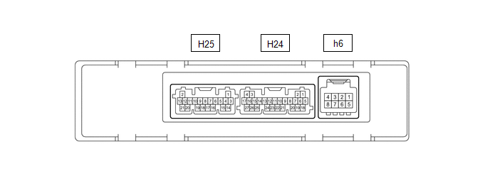
CHECK AIR CONDITIONING AMPLIFIER ASSEMBLY
(a) Check air conditioning amplifier assembly.
(1) Disconnect the H24 air conditioning amplifier assembly connector.
(2) Measure the voltage and resistance according to the value(s) in the table below.
Standard:
| Terminal No. (Symbol) | Terminal Description | Condition | Specified Condition |
|---|---|---|---|
| H24-5 (B) - H24-17 (GND) | Power source | Always | 11 to 14 V |
| H24-6 (IG+) - H24-17 (GND) | Power source (IG) | Ignition switch ON | 11 to 14 V |
| Ignition switch off | Below 1 V | ||
| H24-17 (GND) - Body ground | Ground for main power supply | Always | Below 1 Ω |
(3) Connect the H24 air conditioning amplifier assembly connector.
(4) Measure the voltage, resistance and waveform according to the value(s) in the table below.
Standard:
| Terminal No. (Symbol) | Terminal Description | Condition | Specified Condition |
|---|---|---|---|
| H25-3 (SG-1) - Body ground | Ground for cooler thermistor (room temperature sensor) | Always | Below 1 Ω |
| H25-5 (TR) - H24-17 (GND) | Cooler thermistor (room temperature sensor) signal |
| 1.05 to 1.45 V |
| H25-6 (PRE) - H24-17 (GND) | Air conditioner pressure sensor signal |
| Less than 4.73 V and 0.62 V or higher*1 |
| 4.73 V or higher*1 | ||
| Less than 0.62 V*1 | ||
| H25-11 (S5-3) - H24-17 (GND) | Power supply for air conditioner pressure sensor | Ignition switch ON | 4.75 to 5.25 V |
| Ignition switch off | Below 1 V | ||
| H25-15 (SG-4) - Body ground | Ground for air conditioner pressure sensor | Always | Below 1 Ω |
| H24-1 (CANL) - H24-17 (GND) | CAN communication system | Ignition switch ON | Pulse generation |
| H24-2 (CANH) - H24-17 (GND) | CAN communication system | Ignition switch ON | Pulse generation |
| H24-7 (LIN1) - H24-17 (GND) | LIN communication signal | Ignition switch ON | Pulse generation (See waveform 1) |
| H24-18 (SOL+) - H24-17 (GND) | Compressor solenoid operation signal |
| Pulse generation (See waveform 2) |
| H24-21 (BLW) - H24-17 (GND) | Blower motor speed control signal |
| Pulse generation (See waveform 3) |
| h6-2 (BUSG) - Body ground | Ground for BUS IC | Always | Below 1 Ω |
| h6-3 (BUS) - h6-2 (BUSG) | BUS IC control signal | Ignition switch ON | Pulse generation (See waveform 4) |
| h6-4 (BUSB) - h6-2 (BUSG) | Power supply for BUS IC | Always | 11 to 14 V |
| h6-5 (SG-3) - Body ground | Ground for No. 1 cooler thermistor | Always | Below 1 Ω |
| h6-6 (TE) - h6-5 (SG-3) | No. 1 cooler thermistor signal |
| 1.7 to 2.1 V |
| 0.9 to 1.3 V |
*1: While sensor voltage is 5 V.
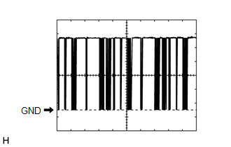
(b) Waveform 1:
| Item | Content |
|---|---|
| Terminal No. | H24-7 (LIN1) - H24-17 (GND) |
| Tool Setting | 2 V/DIV., 20 ms./DIV. |
| Condition | Ignition switch ON |
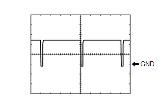
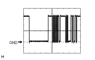
(c) Waveform 2:
| Item | Content |
|---|---|
| Terminal No. | H24-18 (SOL+) - H24-17 (GND) |
| Tool Setting | 5 V/DIV., 500 μs./DIV. |
| Condition |
|
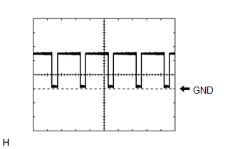
(d) Waveform 3:
| Item | Content |
|---|---|
| Terminal No. | H24-21 (BLW) - H24-17 (GND) |
| Tool Setting | 2 V/DIV., 1 ms./DIV. |
| Condition |
|
HINT:
The waveform varies with the blower speed.
(e) Waveform 4:

| Item | Content |
|---|---|
| Terminal No. | h6-3 (BUS) - h6-2 (BUSG) |
| Tool Setting | 2 V/DIV., 2 ms./DIV. |
| Condition | Ignition switch ON |
CHECK AIR CONDITIONING CONTROL ASSEMBLY

(a) Check air conditioning control assembly.
(1) Disconnect the H31 air conditioning control assembly connector.
(2) Measure the voltage, resistance and waveform according to the value(s) in the table below.
Standard:
| Terminal No. (Symbol) | Terminal Description | Condition | Specified Condition |
|---|---|---|---|
| H31-7 (LIN1) - Body ground | LIN communication signal | Ignition switch ON | Pulse generation (See waveform 1) |
| H31-8 (ILL+) - Body ground | Illumination signal | Taillight off | Below 1 V |
| Taillight on | 11 to 14 V | ||
| H31-9 (IG+) - H31-13 (GND) | Power source (IG) | Ignition switch off | Below 1 V |
| Ignition switch ON | 10.5 to 16 V | ||
| H31-13 (GND) - Body ground | Ground for air conditioning control assembly | Always | Below 1 Ω |
| H31-14 (ILL-) - Body ground | Illumination signal | Always | Below 1 V |
(b) Waveform 1:
| Item | Content |
|---|---|
| Terminal No. | H31-7 (LIN1) - Body ground |
| Tool Setting | 2 V/DIV., 20 ms./DIV. |
| Condition | Ignition switch ON |
 Problem Symptoms Table
PROBLEM SYMPTOMS TABLE NOTICE:
Use the table below to help determine the cause of problem symptoms. If multiple suspected areas are listed, the potential causes of the symptoms are listed in order of probability in the "Suspected Area" column of the table...

Other information:
Toyota Yaris XP210 (2020-2026) Reapir and Service Manual: All Door Entry Lock/Unlock Functions and Wireless Functions do not Operate
DESCRIPTION If the entry lock and wireless door lock operations cannot be performed, the smart door control receiver assembly may be malfunctioning, or there may be wave interference or problems in the communication which is used for the entry and wireless function between the smart door control receiver assembly and certification ECU (smart key ECU assembly)...
Toyota Yaris XP210 (2020-2026) Reapir and Service Manual: Data List / Active Test
DATA LIST / ACTIVE TEST DATA LIST HINT: Using the GTS to read the Data List allows the values or states of switches, sensors, actuators and other items to be read without removing any parts. This non-intrusive inspection can be very useful because intermittent conditions or signals may be discovered before parts or wiring is disturbed...
Categories
- Manuals Home
- Toyota Yaris Owners Manual
- Toyota Yaris Service Manual
- G16e-gts (engine Mechanical)
- Fuse Panel Description
- Engine & Hybrid System
- New on site
- Most important about car
Break-In Period
No special break-in is necessary, but a few precautions in the first 600 miles (1,000 km) may add to the performance, economy, and life of the vehicle.
Do not race the engine. Do not maintain one constant speed, either slow or fast, for a long period of time. Do not drive constantly at full-throttle or high engine rpm for extended periods of time. Avoid unnecessary hard stops. Avoid full-throttle starts.