Toyota Yaris: Can Communication System / Diagnosis System
DIAGNOSIS SYSTEM
NOTICE:
The following communication bus check screen is provided only as an example. This screen differs from the actual screen for this vehicle.
Description of "Communication Bus Check" Screen
HINT:
The ECUs and sensors that are normally connected to the CAN communication system are displayed on the GTS.
(a) Select "Communication Bus Check" on the menu screen of the GTS.
CAN Bus CheckHINT:
If items are not selected correctly in the vehicle specification pop up screen, the name of the CAN junction connector to which the ECUs or sensors are connected may not be displayed on the "Communication Bus Check" screen.
(b) Confirm that the "Communication Bus Check" screen is displayed and the ECUs and sensors that have a history of being connected to the monitoring ECU are displayed.
HINT:
- Even if an ECU or sensor that is connected to a bus that is monitored by a bus monitoring ECU (gateway function equipped ECU) is not communicating, it will remain displayed on the "Communication Bus Check" screen.
- When an ECU or sensor that is connected to a bus that is not monitored by a bus monitoring ECU (gateway function equipped ECU) is not displayed on the "Communication Bus Check" screen, it means that it is not communicating.
- ECUs with a history of being connected are displayed even if the ECUs are removed.
(c) The default display setting selected on the combo box is ALL. When checking for ECUs or sensors for a specific bus, choose the bus from the drop down list. ALL, each bus, each sub bus and Central Gateway are listed in the drop down list.
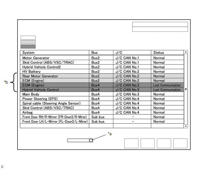
| *a | Combo box | *b | Background color is red or yellow |
| Item | Detail |
|---|---|
| Combo box: ALL | Displays all ECUs and sensors connected to the central bus and sub buses. |
| Combo box: Bus | Displays ECUs and sensors connected to the selected bus. |
| Combo box: Sub bus | Displays ECUs and sensors connected to the selected sub bus. |
| Combo box: Central Gateway | Displays all ECUs and sensors connected to the central bus. |
NOTICE:
- When using the combo box, it may be possible to select a sub bus from the drop down list that does not have any connected ECUs or sensors. This is not a malfunction and occurs when there is no optional device connected to a sub bus which is monitored by a sub bus monitoring ECU (gateway function equipped ECU).
-
In the drop down list, all sub buses applicable to the model are displayed (e.g. LIN communication sub buses are also displayed). For information on sub buses necessary to diagnose the CAN communication system, refer to System Diagram.
Click here

HINT:
The background color of an ECU or sensor changes according to its connection status as indicated in the following table.
Description of "Communication Bus Check" Screen| Bus Type | Background Color | Connection Status |
|---|---|---|
| Bus | White | Communication has been normal. |
| Yellow | Communication stop occurred at least once since the start of the CAN bus check, but communication is currently occurring (unstable communication). | |
| Red | Currently not communicating (either of the following):
| |
| Not displayed | Either of the following:
| |
| Sub bus with a gateway function equipped ECU that does not memorize connected ECUs or sensors*2 | White | Communication has been normal since the start of the CAN bus check. |
| Yellow | Communication stop occurred at least once since the start of the CAN bus check, but communication is currently occurring (unstable communication). | |
| Red | Communication occurred at least once since the start of the CAN bus check, but is currently not occurring. | |
| Not displayed | Communication stop has continued since the start of the CAN bus check.*1 | |
| Sub bus with a gateway function equipped ECU that memorizes connected ECUs and sensors*3 | White | Communication has been normal. |
| Yellow | Communication stop occurred at least once since the start of the CAN bus check, but communication is currently occurring (unstable communication). | |
| Red | Currently not communicating (either of the following):
| |
| Not displayed | Either of the following:
|
- Gateway function equipped ECUs relay signals between ECUs and sensors connected to different buses.
- *1: An ECU or sensor is installed to the vehicle but is not displayed on the "Communication Bus Check" screen.
- *2: The gateway function equipped ECU does not memorize ECUs and sensors connected to its respective sub bus.
- *3: The gateway function equipped ECU memorizes ECUs and sensors connected to its respective sub bus.
- *4: When the central gateway ECU (network gateway ECU) has an internal malfunction or cannot communicate with the GTS, the name of buses, sub buses, ECUs and sensors will not be displayed.
- *5: When no ECUs or sensors are connected to a bus, the message "There is no system found on the communication Bus." will be displayed.
- *6: When a gateway function equipped ECU cannot communicate with the central gateway ECU (network gateway ECU), the name of sub buses and ECUs or sensors connected to the sub bus will not be displayed.
- *7: When no ECUs or sensors are connected to the sub bus, the message "There is no system found on the communication Bus." will be displayed.
- If there is no communication between the GTS and the vehicle, or no ECUs or sensors are displayed as connected, check the central gateway ECU (network gateway ECU) and diagnosis bus (The bus that connects the DLC3 to the central gateway ECU (network gateway ECU)) for malfunctions.
(d) Monitor the screen for any ECU or sensor connection status changes for a period of 2 minutes.
HINT:
- If an open occurs in one of the wires of a CAN branch line, it may interfere with the communication of other ECUs or sensors resulting in an incorrect state being displayed.
- If the connection status changes intermittently during the inspection, repair the open in the branch line of the ECU or sensor that is not communicating, and then perform Communication Bus Check again.
NOTICE:
The following communication bus check screen is provided only as an example. This screen differs from the actual screen for this vehicle.
Description of "Communication Bus Check (Detail)" Screen
HINT:
The communication error history of ECUs or sensors which have communication error history can be displayed on the "Communication Bus Check (Detail)" screen.
(a) Select "Communication Bus Check" on the menu screen of the GTS.
CAN Bus CheckHINT:
If items are not selected correctly in the vehicle specification pop up screen, the name of the CAN junction connector to which the ECUs or sensors are connected may not be displayed on the "Communication Bus Check" screen.
(b) Select "Detail" on the "Communication Bus Check" screen.

| *a | Communication Bus Check (Detail) | - | - |
(c) Confirm that the "Communication Bus Check (Detail)" screen is displayed and the communication error history of the ECUs or sensors up to present is displayed.
HINT:
- Lost Communication Time and Lost Communication Trip are only displayed for the central bus.
- Lost Communication Time and Lost Communication Trip are not displayed for sub buses.
(d) The default display setting selected on the combo box is ALL. When checking for ECUs or sensors for a specific bus, choose the bus from the drop down list. ALL, each bus, each sub bus and Central Gateway are listed in the drop down list.
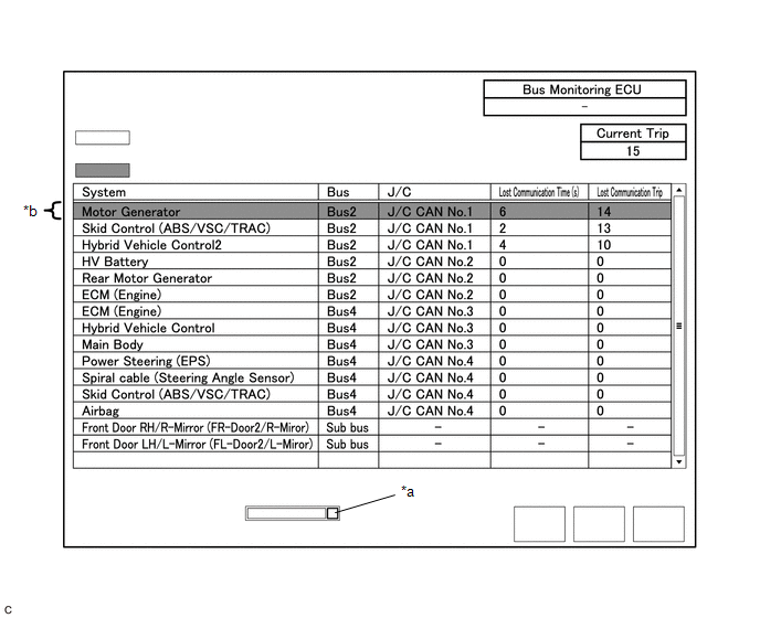
| *a | Combo box | *b | Background color is red |
| Item | Detail |
|---|---|
| Combo box: ALL | Displays all ECUs and sensors connected to the central bus and sub buses. |
| Combo box: Bus | Displays ECUs and sensors connected to the selected bus. |
| Combo box: Sub bus | Displays ECUs and sensors connected to the selected sub bus. |
| Combo box: Central Gateway | Displays all ECUs and sensors connected to the central bus. |
| Bus Monitoring ECU | Displays the gateway function equipped ECU which monitors the selected bus or sub bus. |
| Current Trip | Displays the total number of trips up to now* |
| Lost Communication Time(s) | Displays the longest period of time in seconds that the ECU or sensor connected to the central bus was not communicating. |
| Lost Communication Trip | Displays the trip in which the longest period of time that the ECU or sensor connected to the central bus was not communicating occurred. |
- *: If the component has been replaced with a new one, the total number of trips after the replacement is displayed.
NOTICE:
- The Lost Communication Time column displays the longest period of time in seconds that the central gateway ECU (network gateway ECU) detected a communication stop in the respective ECU or sensor.
- The Lost Communication Trip column displays the trip in which the central gateway ECU (network gateway ECU) detected the longest communication stop in the respective ECU or sensor.
- When using the combo box, it may be possible to select a sub bus from the drop down list that does not have any connected ECUs or sensors. This is not a malfunction and occurs when there is no optional device connected to a sub bus which is monitored by a sub bus monitoring ECU (gateway function equipped ECU).
-
In the drop down list, all sub buses applicable to the model are displayed (e.g. LIN communication sub buses are also displayed). For information on sub buses necessary to diagnose CAN communication system, refer to the System Diagram.
Click here

HINT:
The background color of an ECU or sensor changes according to its connection status as indicated in the following table.
Description of "Communication Bus Check (Detail)" Screen| Bus Type | Background Color | Connection Status |
|---|---|---|
| Bus | White | Either of the following:
|
| Red | Lost Communication Time is 6 seconds or more. | |
| Not displayed | Either of the following:
| |
| Sub bus | White | Lost Communication Time is displayed as "-". |
| Not displayed | Either of the following:
|
- If there is no communication between the GTS and the vehicle, or no ECUs or sensors are displayed as connected, check the central gateway ECU (network gateway ECU) and diagnosis bus (The bus that connects the DLC3 to the central gateway ECU (network gateway ECU)) for malfunctions.
- Lost Communication Time and Lost Communication Trip are not displayed for sub buses.
- *1: When the central gateway ECU (network gateway ECU) has an internal malfunction or cannot communicate with the GTS, the name of buses, sub buses, ECUs and sensors will not be displayed.
- *2: When no ECUs or sensors are connected to a bus, the message "There is no system found on the communication Bus." will be displayed.
- *3: When a gateway function equipped ECU cannot communicate with the central gateway ECU (network gateway ECU), the name of sub buses and ECUs or sensors connected to the sub bus will not be displayed.
- *4: When no ECUs or sensors are connected to the sub bus, the message "There is no system found on the communication Bus." will be displayed.
Communication Bus Check (Communication Malfunction Check)
HINT:
DTCs related to CAN communication are displayed for each ECU on the GTS.
(a) Select "Communication Bus Check" on the menu screen of the GTS.
CAN Bus Check(b) Select "Communication Malfunction Check" on the "Communication Bus Check" screen.
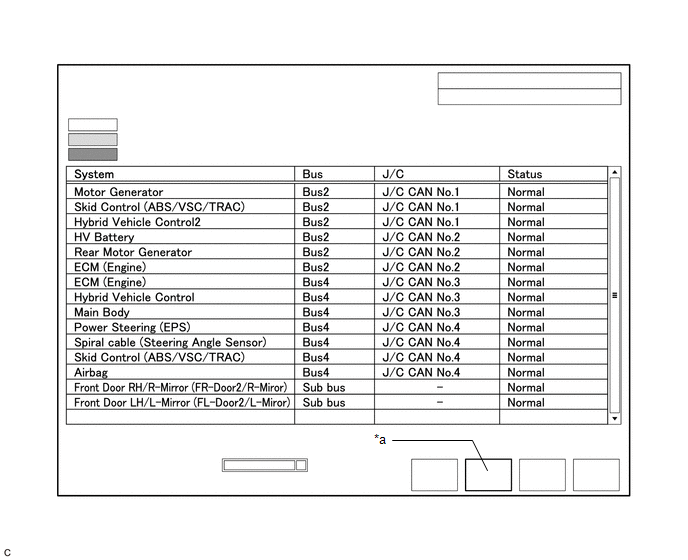
| *a | Communication Malfunction Check | - | - |
(c) Confirm that the "Communication Malfunction Check" screen is displayed and CAN communication DTCs for each ECU are displayed.
HINT:
When there are no CAN communication DTCs stored, no DTCs will be displayed.
How to Use "Communication Bus Check" Screen in Inspection
NOTICE:
The following CAN bus wiring diagram or communication bus check screen is provided only as an example. This wiring diagram or screen differs from the actual one for this vehicle.
HINT:
- If the CAN communication system is currently malfunctioning, it is recommended to use Communication Bus Check rather than Communication DTCs for determining the suspected area.
- Turn the ignition switch to ON, or perform the necessary operations to reproduce the problem symptom, select "Communication Bus Check" and wait approximately 2 minutes. Check the communication status of each ECU or sensor on the screen while performing this operation.
(a) If the CAN communication system is currently malfunctioning, determine the suspected area using Communication Bus Check as follows:
Problem Symptoms Table| Problem Symptom Pattern | Display on Communication Bus Check Screen | Suspected Area |
|---|---|---|
| A | Almost all of the ECUs and sensors connected to the malfunctioning CAN bus are displayed as not communicating on the "Communication Bus Check" screen. |
|
| B | ECUs or sensors farther from the central gateway ECU (network gateway ECU) than the open in the wires are displayed as not communicating on the "Communication Bus Check" screen. | Open in both wires of a main bus line in the central bus |
| C | One ECU or sensor is displayed as not communicating on the "Communication Bus Check" screen. |
|
| D |
|
|
| E | One ECU or sensor is displayed as not communicating in multiple buses on the "Communication Bus Check" screen. |
|
| F | Some ECUs or sensors are displayed as not communicating in the central bus and other ECUs or sensors are displayed as not communicating in a sub bus. |
|
| G | A gateway function equipped ECU is displayed as not communicating in the central bus and ECUs and sensors connected to its respective sub bus are not displayed. |
|
| H | One ECU or sensor is displayed as not communicating in a sub bus on the "Communication Bus Check" screen. |
|
| I | ECUs or sensors farther from the sub bus monitoring ECU (gateway function equipped ECU) than the open in the wires are displayed as not communicating on the "Communication Bus Check" screen. | Open in both wires of a main bus line in a sub bus |
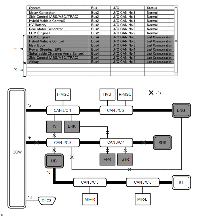
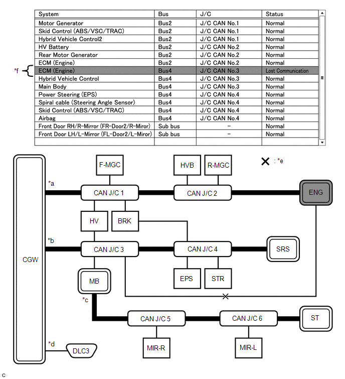
(b) Problem Symptom Pattern A
| Display on Communication Bus Check Screen | Almost all of the ECUs and sensors connected to the malfunctioning CAN bus are displayed as not communicating on the "Communication Bus Check" screen. |
| Details of Malfunction |
|
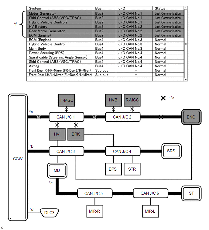
| *a | Bus 2 | *b | Bus 4 |
| *c | Sub bus | *d | Diagnosis bus |
| *e | Location of malfunction
| *f | Background color is red |
HINT:
- Due to the malfunction, almost all of the ECUs and sensors connected to Bus 2 will be displayed as not communicating and their background color will be red.
- The malfunction in Bus 2 will not affect the other buses.
- The malfunctioning part can be determined by inspecting for an open in the main bus line, a short between bus lines or a short to +B or ground.
- Make sure to perform the inspection to measure resistances of buses to determine the cause of the malfunction.
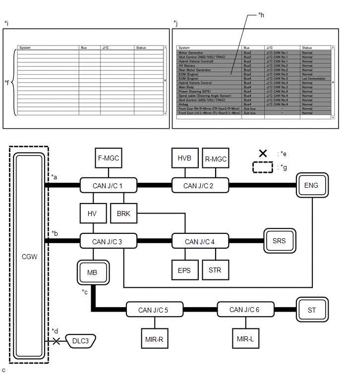
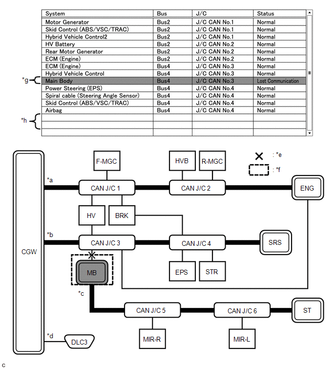
| Display on Communication Bus Check Screen | Almost all of the ECUs and sensors connected to the malfunctioning CAN bus are displayed as not communicating on the "Communication Bus Check" screen. |
| Details of Malfunction |
|
| *a | Bus 2 | *b | Bus 4 |
| *c | Sub bus | *d | Diagnosis bus |
| *e | Location of malfunction
| *f | Background color is red |
| *g | Not displayed | - | - |
HINT:
- Due to the malfunction, almost all of the ECUs and sensors connected to Bus 4 will be displayed as not communicating and their background color will be red.
- The malfunction will not affect the other buses of the central bus. However, the sub bus connected to Bus 4 is likely to be affected. The gateway function equipped ECU connected to Bus 4 will not communicate and consequently the sub bus and its respective ECUs or sensors monitored by the gateway function equipped ECU (sub bus monitoring ECU) will not be displayed, indicating that the gateway function equipped ECU is not communicating with the central gateway ECU (network gateway ECU).
- The malfunctioning part can be determined by inspecting for an open in the main bus line, a short between bus lines or a short to +B or ground.
- Make sure to perform the inspection to measure resistances of buses to determine the cause of the malfunction.
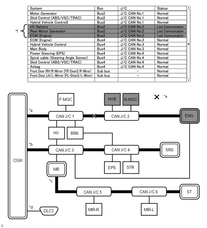
(c) Problem Symptom Pattern B
| Display on Communication Bus Check Screen | ECUs or sensors farther from the central gateway ECU (network gateway ECU) than the open in the wires are displayed as not communicating on the "Communication Bus Check" screen. |
| Details of Malfunction | Open in both wires of the main bus line between CGW and No. 1 CAN junction connector in Bus 2 |

| *a | Bus 2 | *b | Bus 4 |
| *c | Sub bus | *d | Diagnosis bus |
| *e | Location of malfunction (open in both wires of the main bus line) | *f | Background color is red |
HINT:
- Due to the malfunction, almost all of the ECUs and sensors connected to Bus 2 will be displayed as not communicating and their background color will be red.
- The malfunction in Bus 2 will not affect the other buses.
- The malfunctioning part can be determined by inspecting for an open in the main bus line.
- Make sure to perform the inspection to measure resistances of buses to determine the cause of the malfunction.
| Display on Communication Bus Check Screen | ECUs or sensors farther from the central gateway ECU (network gateway ECU) than the open in the wires are displayed as not communicating on the "Communication Bus Check" screen. |
| Details of Malfunction | Open in both wires of the main bus line between the No. 1 CAN junction connector and No. 2 CAN junction connector in Bus 2 |
| *a | Bus 2 | *b | Bus 4 |
| *c | Sub bus | *d | Diagnosis bus |
| *e | Location of malfunction (open in both wires of the main bus line) | *f | Background color is red |
HINT:
- Due to the malfunction, ECUs or sensors farther from CGW than the open in the wires will be displayed as not communicating and their background color will be red.
- The malfunction in Bus 2 will not affect the other buses.
- The malfunctioning part can be determined by inspecting for an open in the main bus line.
- Make sure to perform the inspection to measure resistances of buses to determine the cause of the malfunction.
| Display on Communication Bus Check Screen | ECUs or sensors farther from the central gateway ECU (network gateway ECU) than the open in the wires are displayed as not communicating on the "Communication Bus Check" screen. |
| Details of Malfunction | Open in both wires of the main bus line between the No. 2 CAN junction connector and ENG in Bus 2 |
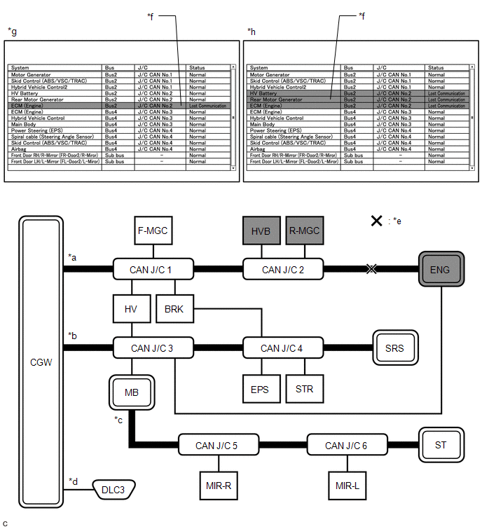
| *a | Bus 2 | *b | Bus 4 |
| *c | Sub bus | *d | Diagnosis bus |
| *e | Location of malfunction (open in both wires of the main bus line) | *f | Background color is red |
| *g | Pattern 1 | *h | Pattern 2 |
HINT:
- Even when the same part of the main bus line is open, depending on internal electrical noise which changes according to the position of the open in the line, the information displayed on the "Communication Bus Check" screen may differ.
- In pattern 2, the information displayed may be the same as when there is an open in both wires in the main bus line between the No. 1 CAN junction connector and No. 2 CAN junction connector, which may make it difficult to determine the malfunctioning part.
- The malfunction in Bus 2 will not affect the other buses.
- Make sure to perform the inspection to measure resistances of buses to determine the cause of the malfunction.
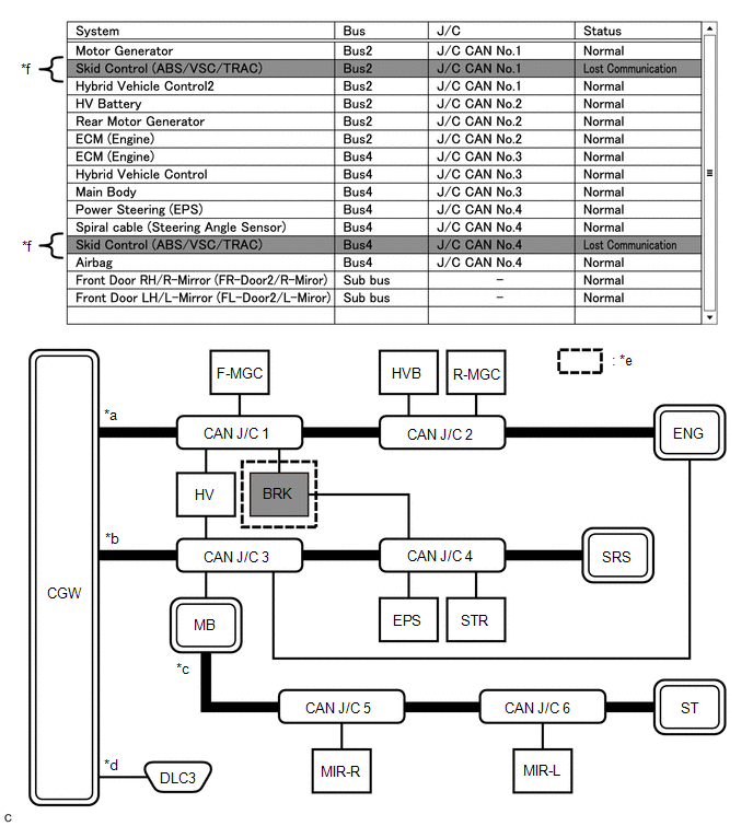
(d) Problem Symptom Pattern C
| Display on Communication Bus Check Screen | One ECU or sensor is displayed as not communicating on the "Communication Bus Check" screen. |
| Details of Malfunction |
|
| *a | Bus 2 | *b | Bus 4 |
| *c | Sub bus | *d | Diagnosis bus |
| *e | Location of malfunction 1 (open in both wires of the branch line) | *f | Background color is red |
| *g | Location of malfunction 2
| - | - |
HINT:
The information displayed on the "Communication Bus Check" screen will be the same for an open in both wires of a branch line, an internal malfunction of an ECU or sensor or a malfunction in the power supplied to an ECU or sensor. In this example, the background color of the malfunctioning ECU or sensor will be red.
| Display on Communication Bus Check Screen | One ECU or sensor is displayed as not communicating on the "Communication Bus Check" screen. |
| Details of Malfunction | Open in both wires of the branch line connected to ENG in Bus 4 |
| *a | Bus 2 | *b | Bus 4 |
| *c | Sub bus | *d | Diagnosis bus |
| *e | Location of malfunction (open in both wires of the branch line) | *f | Background color is red |
HINT:
- The malfunction in Bus 4 will not affect the other buses.
- Due to the malfunction, although ENG is communicating normally with CGW via Bus 2, it is not communicating with CGW via Bus 4. Consequently, it will be displayed as not communicating in Bus 4.
(e) Problem Symptom Pattern D
| Display on Communication Bus Check Screen |
|
| Details of Malfunction |
|
| *a | Bus 2 | *b | Bus 4 |
| *c | Sub bus | *d | Diagnosis bus |
| *e | Location of malfunction 1 (open in both wires of the branch line) | *f | Not displayed |
| *g | Location of malfunction 2 (Internal malfunction) | *h | Background color is red |
| *i | Pattern 1 (Malfunction occurred before CAN bus check) | *j | Pattern 2 (Malfunction occurred after CAN bus check) |
HINT:
When there is no communication between the GTS and the vehicle, no ECUs or sensors will be displayed.
(f) Problem Symptom Pattern E
| Display on Communication Bus Check Screen | One ECU or sensor is displayed as not communicating in multiple buses on the "Communication Bus Check" screen. |
| Details of Malfunction |
|
| *a | Bus 2 | *b | Bus 4 |
| *c | Sub bus | *d | Diagnosis bus |
| *e | Location of malfunction
| *f | Background color is red |
HINT:
The information displayed on the "Communication Bus Check" screen will be the same for an internal malfunction of an ECU or sensor, or a malfunction in the power supplied to an ECU or sensor.
Due to the malfunction, BRK is not communicating with CGW via both Bus 2 and Bus 4. Consequently, the background color of BRK will be red for both Bus 2 and Bus 4.
(g) Problem Symptom Pattern F
| Display on Communication Bus Check Screen | Some ECUs or sensors are displayed as not communicating in the central bus and other ECUs or sensors are displayed as not communicating in a sub bus. |
| Details of Malfunction |
|
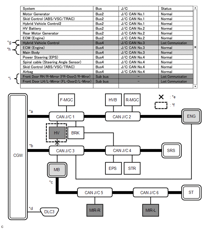
| *a | Bus 2 | *b | Bus 4 |
| *c | Sub bus | *d | Diagnosis bus |
| *e | Location of malfunction 1 (open in a wire of the branch line) | *f | Location of malfunction 2
|
| *g | Background color is red | *h | Background color intermittently becomes yellow or red |
| *i | Not displayed or background color is yellow or red | - | - |
HINT:
- In the "Communication Bus Check" screen shown in the illustration, electrical noise in the CAN bus caused by an open in a wire in the branch line connected to HV interferes with the communication of MB causing unstable communication. Also, since MB is a gateway function equipped ECU, communication of ECUs connected to its respective sub bus will also be unstable.
- In the "Communication Bus Check" screen shown in the illustration, because the background color of HV is red, it is suspected that HV is the most likely cause of the malfunction. Therefore, it is suspected that HV is not communicating.
(h) Problem Symptom Pattern G
| Display on Communication Bus Check Screen | A gateway function equipped ECU is displayed as not communicating in the central bus and ECUs and sensors connected to its respective sub bus are not displayed. |
| Details of Malfunction |
|
| *a | Bus 2 | *b | Bus 4 |
| *c | Sub bus | *d | Diagnosis bus |
| *e | Location of malfunction 1 (open in both wires of the branch line) | *f | Location of malfunction 2
|
| *g | Background color is red | *h | Not displayed |
HINT:
- If there is a communication malfunction in a gateway function equipped ECU, ECUs connected to its respective sub bus will also be affected and will not be displayed.
- In the "Communication Bus Check" screen shown in the illustration, MB is a gateway function equipped ECU. Therefore, MB is suspected as not communicating.
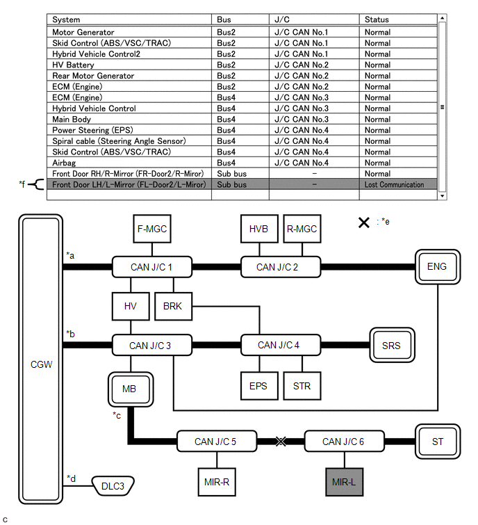
(i) Problem Symptoms Pattern H
| Display on Communication Bus Check Screen | One ECU or sensor is displayed as not communicating in a sub bus on the "Communication Bus Check" screen. |
| Details of Malfunction |
|

| *a | Bus 2 | *b | Bus 4 |
| *c | Sub bus | *d | Diagnosis bus |
| *e | Location of malfunction 1 (open in both wires of the branch line) | *f | Location of malfunction 2
|
| *g | Background color is red | - | - |
HINT:
- The malfunction in the sub bus will not affect the other buses.
- When a gateway function equipped ECU memorizes ECUs and sensors connected to its respective sub bus and there is a communication malfunction in one of the ECUs or sensors, the background color of the ECU or sensor will change to red and the ECU or sensor will remain displayed.
- The information displayed on the "Communication Bus Check" screen will be the same for an open in both wires of a branch line, an internal malfunction of an ECU or sensor or a malfunction in the power supplied to an ECU or sensor.
(j) Problem Symptom Pattern I
| Display on Communication Bus Check Screen | ECUs or sensors farther from the sub bus monitoring ECU (gateway function equipped ECU) than the open in the wires are displayed as not communicating on the "Communication Bus Check" screen. |
| Details of Malfunction | Open in both wires of the main bus line in the sub bus |
| *a | Bus 2 | *b | Bus 4 |
| *c | Sub bus | *d | Diagnosis bus |
| *e | Location of malfunction (open in both wires of the main bus line) | *f | Background color is red |
HINT:
Due to the malfunction, ECUs or sensors farther from the sub bus monitoring ECU (gateway function equipped ECU) than the open in the wires will be displayed as not communicating and their background color will be red.
How to Use "Communication Bus Check (Detail)" Screen in Inspection
(a) Even if the malfunction cannot be determined on the "Communication Bus Check" screen, determine the malfunctioning part using Communication Bus Check (Detail) as follows:
NOTICE:
- The following CAN bus wiring diagram or communication bus check screen is provided only as an example. This wiring diagram or screen differs from the actual one for this vehicle.
- The Lost Communication Time column displays the longest period of time in seconds that the central gateway ECU (network gateway ECU) detected a communication stop in the respective ECU or sensor.
- The Lost Communication Trip column displays the trip in which the central gateway ECU (network gateway ECU) detected the longest communication stop in the respective ECU or sensor.
- When using the combo box, it may be possible to select a sub bus from the drop down list that does not have any connected ECUs or sensors. This is not a malfunction and occurs when there is no optional device connected to a sub bus which is monitored by a sub bus monitoring ECU (gateway function equipped ECU).
-
In the drop down list, all sub buses applicable to the model are displayed (e.g. LIN communication sub buses are also displayed). For information on sub buses necessary to diagnose CAN communication system, refer to the System Diagram.
Click here

HINT:
- If the CAN communication system is currently malfunctioning, it is recommended to use Communication Bus Check rather than Communication Bus Check (Detail) for determining the suspected area.
- The communication error history of ECUs or sensors which have communication error history can be displayed on the "Communication Bus Check (Detail)" screen.
- Lost Communication Time and Lost Communication Trip are only displayed for the central bus.
- Lost Communication Time and Lost Communication Trip are not displayed for sub buses.
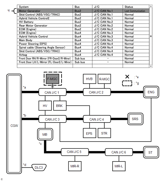
(b) If there is an ECU or sensor displayed with a red background on the "Communication Bus Check (Detail)" screen to indicate that it was not communicating, it is suspected that the ECU or sensor was not communicating.
| Details of Malfunction | Past malfunction in the wire harness or power supplied to F-MGC in Bus 2 |
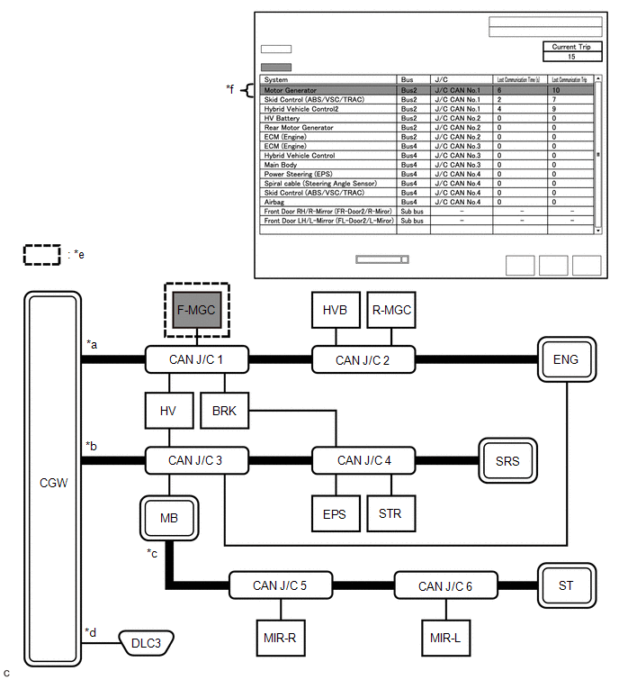
| *a | Bus 2 | *b | Bus 4 |
| *c | Sub bus | *d | Diagnosis bus |
| *e | Location of malfunction
| *f | Background color is red |
| Bus Type | Background Color | Connection Status |
|---|---|---|
| Bus | White | Either of the following:
|
| Red | Lost Communication Time is 6 seconds or more. | |
| Not displayed | Either of the following:
| |
| Sub bus | White | Lost Communication Time is displayed as "-". |
| Not displayed | Either of the following:
|
HINT:
- Check the values of Lost Communication Trip and Current Trip for the ECUs or sensors that have a red background color.
- If the values of Lost Communication Trip and Current Trip are the same for an ECU or sensor, the ECU or sensor is currently not communicating. In this case, it is recommended to use Communication Bus Check rather than Communication Bus Check (Detail) for determining the suspected area.
- In the "Communication Bus Check (Detail)" screen shown in the illustration, F-MGC had a communication malfunction in the 10th trip. Thus, it is suspected that F-MGC was not communicating.
- *1: When the central gateway ECU (network gateway ECU) has an internal malfunction or cannot communicate with the GTS, the name of buses, sub buses, ECUs and sensors will not be displayed.
- *2: When no ECUs or sensors are connected to a bus, the message "There is no system found on the communication Bus." will be displayed.
- *3: When a gateway function equipped ECU cannot communicate with the central gateway ECU (network gateway ECU), the name of sub buses and ECUs or sensors connected to the sub bus will not be displayed.
- *4: When no ECUs or sensors are connected to the sub bus, the message "There is no system found on the communication Bus." will be displayed.
DTC TABLE BY ECU
HINT:
- In the CAN communication system, the CAN communication DTCs of each ECU can be displayed using the GTS.
-
If CAN communication system DTCs are output, the malfunction cannot be determined only by the DTCs. Perform troubleshooting according to How to Proceed with Troubleshooting.
Click here

- If there is a malfunction currently, DTCs can be checked by performing steps in the DTC check procedure.
(a) ECM / GTS Display "Engine"
Powertrain > Engine > Trouble CodesHINT:
This ECU uses the CAN communication system for DTC communication.
| DTC | Detection Item | DTC Detection Condition | DTC Detection Pre-condition | DTC Check Procedure | Warning Displayed | DTC Storage Method | |
|---|---|---|---|---|---|---|---|
| Indication in Meter | Multi-information Display | ||||||
| U012987 | Lost Communication with Brake System Control Module Missing Message | Communication stops between the ECM and the brake actuator assembly for approximately 5 seconds or more. | All conditions are met:
| Turn the ignition switch to ON and wait for at least approximately 7 seconds. | - | - | DTC is stored until it is cleared using the GTS. |
| U110387 | Lost Communication with Stop and Start Control Module Missing Message | Communication stops between the ECM and the engine stop and start ECU for approximately 2 seconds or more. | All conditions are met:
| Turn the ignition switch to ON and wait for at least approximately 3 seconds. | - | - | DTC is stored until it is cleared using the GTS. |
(b) ECM / GTS Display "Radar Cruise1" (w/ Toyota Safety Sense)
Powertrain > Radar Cruise1 > Trouble CodesHINT:
This ECU uses the CAN communication system for DTC communication.
| DTC | Detection Item | DTC Detection Condition | DTC Detection Pre-condition | DTC Check Procedure | Warning Displayed | DTC Storage Method | |
|---|---|---|---|---|---|---|---|
| Indication in Meter | Multi-information Display | ||||||
| U010087 | Lost Communication with ECM/PCM "A" Missing Message | Communication stops between the ECM and the brake actuator assembly for approximately 1 second or more. | All conditions are met:
| Turn the dynamic radar cruise control system on and wait for approximately 3 seconds or more. | - | Displays messages on the multi-information display. | DTC is stored until it is cleared using the GTS. |
| U010487 | Lost Communication with Cruise Control Module Missing Message | Communication stops between the ECM and the millimeter wave radar sensor assembly for approximately 1 second or more. | All conditions are met:
| Turn the dynamic radar cruise control system on and wait for approximately 3 seconds or more. | - | Displays messages on the multi-information display. | DTC is stored until it is cleared using the GTS. |
| U012287 | Lost Communication with Vehicle Dynamics Control Module Missing Message | Communication stops between the ECM and the brake actuator assembly for approximately 3 seconds or more. | All conditions are met:
| Turn the dynamic radar cruise control system on and wait for approximately 3 seconds or more. | - | Displays messages on the multi-information display. | DTC is stored until it is cleared using the GTS. |
| U015500 | Lost Communication with Instrument Panel Cluster (IPC) Control Module | Communication stops between the ECM and the combination meter assembly for approximately 2 seconds or more. | All conditions are met:
| Turn the dynamic radar cruise control system on and wait for approximately 7 seconds or more. | - | Displays messages on the multi-information display. | DTC is stored until it is cleared using the GTS. |
(c) Engine Stop and Start ECU / GTS Display "Stop and Start"
Powertrain > Stop and Start > Trouble CodesHINT:
This ECU uses the CAN communication system for DTC communication.
| DTC | Detection Item | DTC Detection Condition | DTC Detection Pre-condition | DTC Check Procedure | Warning Displayed | DTC Storage Method | |
|---|---|---|---|---|---|---|---|
| Indication in Meter | Multi-information Display | ||||||
| U010087 | Lost Communication with ECM/PCM "A" Missing Message | Communication stops between the engine stop and start ECU and the ECM for approximately 1 second or more. | All conditions are met:
| Turn the ignition switch to ON and wait for at least approximately 5 seconds. | Stop and start cancel indicator light flashes. | - | DTC is stored until it is cleared using the GTS. |
| U012687 | Lost Communication with Steering Angle Sensor Module Missing Message | Communication stops between the engine stop and start ECU and the steering sensor for approximately 3 seconds or more. | All conditions are met:
| Turn the ignition switch to ON and wait for at least approximately 9 seconds. | Stop and start cancel indicator light flashes. | - | DTC is stored until it is cleared using the GTS. |
| U012987 | Lost Communication with Brake System Control Module Missing Message | Communication stops between the engine stop and start ECU and the brake actuator assembly for approximately 3 seconds or more. | All conditions are met:
| Turn the ignition switch to ON and wait for at least approximately 8 seconds. | Stop and start cancel indicator light flashes. | - | DTC is stored until it is cleared using the GTS. |
| U013187 | Lost Communication with Power Steering Control Module Missing Message | Communication stops between the engine stop and start ECU and the power steering ECU assembly for approximately 3 seconds or more. | All conditions are met:
| Turn the ignition switch to ON and wait for at least approximately 9 seconds. | Stop and start cancel indicator light flashes. | - | DTC is stored until it is cleared using the GTS. |
| U014087 | Lost Communication with Body Control Module Missing Message | Communication stops between the engine stop and start ECU and the main body ECU (multiplex network body ECU) for approximately 4 seconds or more. | All conditions are met:
| Turn the ignition switch to ON and wait for at least approximately 11 seconds. | Stop and start cancel indicator light flashes. | - | DTC is stored until it is cleared using the GTS. |
| U015187 | Lost Communication with Restraints Control Module Missing Message | Communication stops between the engine stop and start ECU and the airbag sensor assembly for approximately 11 seconds or more. | All conditions are met:
| Turn the ignition switch to ON and wait for at least approximately 25 seconds. | Stop and start cancel indicator light flashes. | - | DTC is stored until it is cleared using the GTS. |
| U015587 | Lost Communication with Instrument Panel Cluster (IPC) Control Module Missing Message | Communication stops between the engine stop and start ECU and the combination meter assembly for approximately 4 seconds or more. | All conditions are met:
| Turn the ignition switch to ON and wait for at least approximately 11 seconds. | Stop and start cancel indicator light flashes. | - | DTC is stored until it is cleared using the GTS. |
| U016487 | Lost Communication with HVAC Control Module Missing Message | Communication stops between the engine stop and start ECU and the air conditioning amplifier assembly for approximately 11 seconds or more. | All conditions are met:
| Turn the ignition switch to ON and wait for at least approximately 25 seconds. | Stop and start cancel indicator light flashes. | - | DTC is stored until it is cleared using the GTS. |
| U117087 | Lost Communication With Brake System Control Module(ch2) Missing Message | Communication stops between the engine stop and start ECU and the brake actuator assembly for approximately 3 seconds or more. | All conditions are met:
| Turn the ignition switch to ON and wait for at least approximately 8 seconds. | Stop and start cancel indicator light flashes. | - | DTC is stored until it is cleared using the GTS. |
(d) Brake Actuator Assembly / GTS Display "Brake"
Chassis > Brake > Trouble CodesHINT:
This ECU uses the CAN communication system for DTC communication.
| DTC | Detection Item | DTC Detection Condition | DTC Detection Pre-condition | DTC Check Procedure | Warning Displayed | DTC Storage Method | |
|---|---|---|---|---|---|---|---|
| Indication in Meter | Multi-information Display | ||||||
| U010087 | Lost Communication with ECM/PCM "A" Missing Message | Communication stops between the brake actuator assembly and the ECM for approximately 2 seconds or more. | All conditions are met:
| Turn the ignition switch to ON and wait for at least approximately 5 seconds. |
| Displays messages on the multi-information display. | DTC is stored until it is cleared using the GTS. |
| U012587 | Lost Communication with Multi-axis Acceleration Sensor Module Missing Message | Communication stops between the brake actuator assembly and the airbag sensor assembly for approximately 5 seconds or more. | All conditions are met:
| Turn the ignition switch to ON and wait for at least approximately 8 seconds. |
| Displays messages on the multi-information display. | DTC is stored until it is cleared using the GTS. |
| U012687 | Lost Communication with Steering Angle Sensor Module Missing Message | Communication stops between the brake actuator assembly and the steering sensor for approximately 1 second or more. | All conditions are met:
| Turn the ignition switch to ON and wait for at least approximately 4 seconds. | Slip indicator light illuminates. | - | DTC is stored until it is cleared using the GTS. |
| U014087 | Lost Communication with Body Control Module Missing Message | Communication stops between the brake actuator assembly and the main body ECU (multiplex network body ECU) for approximately 2 seconds or more. | All conditions are met:
| Turn the ignition switch to ON and wait for at least approximately 5 seconds. | MIL illuminates. | - | DTC is stored until it is cleared using the GTS. |
| U015187 | Lost Communication with Restraints Control Module Missing Message | Communication stops between the brake actuator assembly and the airbag sensor assembly for approximately 5 seconds or more. | All conditions are met:
| Turn the ignition switch to ON and wait for at least approximately 8 seconds. | - | Displays messages on the multi-information display. | DTC is stored until it is cleared using the GTS. |
| U110787 | Lost Communication with Power Management Module Missing Message | Communication stops between the brake actuator assembly and the certification ECU (smart key ECU assembly) for approximately 3 seconds or more. | All conditions are met:
| Turn the ignition switch to ON and wait for at least approximately 6 seconds. | ABS warning light illuminates. | - | DTC is stored until it is cleared using the GTS. |
| U115C87 | Lost Communication with ECM/PCM A" (ch5)" Missing Message | Communication stops between the brake actuator assembly and the ECM for approximately 2 seconds or more. | All conditions are met:
| Turn the ignition switch to ON and wait for at least approximately 5 seconds. |
| Displays messages on the multi-information display. | DTC is stored until it is cleared using the GTS. |
(e) Power Steering ECU Assembly / GTS Display "EMPS"
Chassis > EMPS > Trouble CodesHINT:
This ECU uses the CAN communication system for DTC communication.
| DTC | Detection Item | DTC Detection Condition | DTC Detection Pre-condition | DTC Check Procedure | Warning Displayed | DTC Storage Method | |
|---|---|---|---|---|---|---|---|
| Indication in Meter | Multi-information Display | ||||||
| U010087 | Lost Communication with ECM/PCM "A" Missing Message | Communication stops between the power steering ECU assembly and the ECM for approximately 300 seconds or more. | All conditions are met:
| Drive the vehicle at a speed of 20 km/h (12 mph) or more for approximately 303 seconds or more. | - | - | DTC is stored until it is cleared using the GTS. |
| U012987 | Lost Communication with Brake System Control Module Missing Message | Communication stops between the power steering ECU assembly and the brake actuator assembly for approximately 10 seconds or more. | All conditions are met:
| Turn the ignition switch to ON and wait for at least approximately 13 seconds. | EPS warning light (yellow) illuminates. | Displays messages on the multi-information display. | DTC is stored until it is cleared using the GTS. |
| U023A87 | Lost Communication with Image Processing Module "A" Missing Message | Communication stops between the power steering ECU assembly and the forward recognition camera for approximately 10 seconds or more. | All conditions are met:
| Turn the ignition switch to ON and wait for at least approximately 13 seconds. | - | - | DTC is stored until it is cleared using the GTS. |
(f) 4WD ECU assembly / GTS Display "Four Wheel Drive"
Chassis > Four Wheel Drive > Trouble CodesHINT:
This ECU uses the CAN communication system for DTC communication.
| DTC | Detection Item | DTC Detection Condition | DTC Detection Pre-condition | DTC Check Procedure | Warning Displayed | DTC Storage Method | |
|---|---|---|---|---|---|---|---|
| Indication in Meter | Multi-information Display | ||||||
| U010087 | Lost Communication with ECM/PCM "A" Missing Message | Communication stops between the 4WD ECU assembly and the ECM for aproximately 5 seconds or more. | All conditions are met:
| Turn the ignition switch to ON and wait for at least approximately 8 seconds. | AWD warning light illuminates. | - | DTC is stored until it is cleared using the GTS. |
| U012687 | Lost Communication with Steering Angle Sensor Module Missing Message | One of the following conditions is met:
| All conditions are met:
| Turn the ignition switch to ON and wait for at least approximately 65 seconds. | AWD warning light illuminates. | - | DTC is stored until it is cleared using the GTS. |
| U012987 | Lost Communication with Brake System Control Module Missing Message | Communication stops between the 4WD ECU assembly and the brake actuator assembly for aproximately 4 seconds or more. | All conditions are met:
| Turn the ignition switch to ON and wait for at least approximately 7 seconds. | AWD warning light illuminates. | - | DTC is stored until it is cleared using the GTS. |
(g) Airbag Sensor Assembly / GTS Display "SRS Airbag"
Body Electrical > SRS Airbag > Trouble CodesHINT:
This ECU uses the CAN communication system for DTC communication.
| DTC | Detection Item | DTC Detection Condition | DTC Detection Pre-condition | DTC Check Procedure | Warning Displayed | DTC Storage Method | |
|---|---|---|---|---|---|---|---|
| Indication in Meter | Multi-information Display | ||||||
| U012987 | Lost Communication with Brake System Control Module "A" Missing Message | Communication stops between the airbag sensor assembly and the brake actuator assembly for approximately 2 seconds or more. | The ignition switch is ON for approximately 3 seconds or more. | Turn the ignition switch to ON and wait for at least approximately 5 seconds. | SRS warning light illuminates. | - | DTC is stored until it is cleared using the GTS. |
| U023587 | Lost Communication with Cruise Control Front Distance Range Sensor Single Sensor or Center Missing Message | Communication stops between the airbag sensor assembly and the millimeter wave radar sensor assembly for approximately 10 seconds or more. | The ignition switch is ON for approximately 3 seconds or more. | Turn the ignition switch to ON and wait for at least approximately 13 seconds. | SRS warning light illuminates. | - | DTC is stored until it is cleared using the GTS. |
| U023A87 | Lost Communication with Image Processing Module "A" Missing Message | Communication stops between the airbag sensor assembly and the forward recognition camera for approximately 10 seconds or more. | The ignition switch is ON for approximately 3 seconds or more. | Turn the ignition switch to ON and wait for at least approximately 13 seconds. | SRS warning light illuminates. | - | DTC is stored until it is cleared using the GTS. |
(h) Millimeter Wave Radar Sensor Assembly / GTS Display "Pre-Collision System" (w/ Toyota Safety Sense)
Body Electrical > Pre-Collision System > Trouble CodesHINT:
- This ECU uses the CAN communication system for DTC communication.
-
*1: Refer to Pre-Collision System.
Click here

| DTC | Detection Item | DTC Detection Condition | DTC Detection Pre-condition | DTC Check Procedure | Warning Displayed | DTC Storage Method | |
|---|---|---|---|---|---|---|---|
| Indication in Meter | Multi-information Display | ||||||
| U010087 | Lost Communication with ECM/PCM "A" Missing Message | Communication stops between the millimeter wave radar sensor assembly and the ECM for approximately 3 seconds or more. | All conditions are met:
| Turn the ignition switch to ON and wait for at least approximately 6 seconds. | PCS warning light illuminates. | Displays messages on the multi-information display. | DTC is stored until it is cleared using the GTS. |
| U012687 | Lost Communication with Steering Angle Sensor Module Missing Message | Communication stops between the millimeter wave radar sensor assembly and the steering sensor for approximately 2 seconds or more. | All conditions are met:
| Turn the ignition switch to ON and wait for at least approximately 5 seconds. | PCS warning light illuminates. | Displays messages on the multi-information display. | DTC is stored until it is cleared using the GTS. |
| U012987 | Lost Communication with Brake System Control Module Missing Message | Communication stops between the millimeter wave radar sensor assembly and the brake actuator assembly for approximately 2 seconds or more. | All conditions are met:
| Turn the ignition switch to ON and wait for at least approximately 5 seconds. | PCS warning light illuminates. | Displays messages on the multi-information display. | DTC is stored until it is cleared using the GTS. |
| U015587 | Lost Communication with Instrument Panel Cluster (IPC) Control Module Missing Message | Communication stops between the millimeter wave radar sensor assembly and the combination meter assembly for approximately 9 seconds or more. | All conditions are met:
| Turn the ignition switch to ON and wait for at least approximately 12 seconds. | PCS warning light illuminates. | Displays messages on the multi-information display. | DTC is stored until it is cleared using the GTS. |
| U023A87*1 | Lost Communication with Image Processing Module "A" Missing Message | Communication stops between the millimeter wave radar sensor assembly and the forward recognition camera for approximately 3 seconds or more. | All conditions are met:
| Turn the ignition switch to ON and wait for at least approximately 6 seconds. | PCS warning light illuminates. | Displays messages on the multi-information display. | DTC is stored until it is cleared using the GTS. |
| U030051*1 | Internal Control Module Software Incompatibility Not Programmed | The control system information sent from the ECM remains undefined by the millimeter wave radar sensor assembly for approximately 3 seconds or more. | All conditions are met:
| Turn the ignition switch to ON and wait for at least approximately 6 seconds. | PCS warning light illuminates. | Displays messages on the multi-information display. | DTC is stored until it is cleared using the GTS. |
| U030057*1 | Internal Control Module Software Incompatibility Invalid / Incompatible Software Component | The control system information sent from the ECM does not match that stored in the millimeter wave radar sensor assembly for approximately 2 seconds or more. | All conditions are met:
| Turn the ignition switch to ON and wait for at least approximately 5 seconds. | PCS warning light illuminates. | Displays messages on the multi-information display. | DTC is stored until it is cleared using the GTS. |
| U041881*1 | Invalid Data Received from Brake System Control Module Invalid Serial Data Received | The millimeter wave radar sensor assembly receives an abnormal brake system control signal for approximately 1 second or more. | All conditions are met:
| Turn the ignition switch to ON and wait for at least approximately 4 seconds. | PCS warning light illuminates. | Displays messages on the multi-information display. | DTC is stored until it is cleared using the GTS. |
(i) Millimeter Wave Radar Sensor Assembly / GTS Display "Radar Cruise2" (w/ Toyota Safety Sense)
Powertrain > Radar Cruise2 > Trouble CodesHINT:
- This ECU uses the CAN communication system for DTC communication.
-
*1: Refer to Dynamic Radar Cruise Control System.
Click here

| DTC | Detection Item | DTC Detection Condition | DTC Detection Pre-condition | DTC Check Procedure | Warning Displayed | DTC Storage Method | |
|---|---|---|---|---|---|---|---|
| Indication in Meter | Multi-information Display | ||||||
| U010087 | Lost Communication with ECM/PCM "A" Missing Message | Communication stops between the millimeter wave radar sensor assembly and the ECM for approximately 1 second or more. | All conditions are met:
| Turn the cruise control main switch on and wait for at least approximately 4 seconds. | - | Displays messages on the multi-information display. | DTC is stored until it is cleared using the GTS. |
| U012687 | Lost Communication with Steering Angle Sensor Module Missing Message | Communication stops between the millimeter wave radar sensor assembly and the steering sensor for approximately 1 second or more. | All conditions are met:
| Turn the cruise control main switch on and wait for at least approximately 4 seconds. | - | Displays messages on the multi-information display. | DTC is stored until it is cleared using the GTS. |
| U012987 | Lost Communication with Brake System Control Module Missing Message | Communication stops between the millimeter wave radar sensor assembly and the brake actuator assembly for approximately 1 second or more. | All conditions are met:
| Turn the cruise control main switch on and wait for at least approximately 4 seconds. | - | Displays messages on the multi-information display. | DTC is stored until it is cleared using the GTS. |
| U015587 | Lost Communication with Instrument Panel Cluster (IPC) Control Module Missing Message | Communication stops between the millimeter wave radar sensor assemblya and the combination meter assembly for approximately 5 seconds or more. | All conditions are met:
| Turn the cruise control main switch on and wait for at least approximately 8 seconds. | - | Displays messages on the multi-information display. | DTC is stored until it is cleared using the GTS. |
| U023A87*1 | Lost Communication with Image Processing Module "A" Missing Message | Communication stops between the millimeter wave radar sensor assembly and the forward recognition camera for approximately 2 seconds or more. | All conditions are met:
| Turn the cruise control main switch on and wait for at least approximately 5 seconds. | - | Displays messages on the multi-information display. | DTC is stored until it is cleared using the GTS. |
| U030051*1 | Internal Control Module Software Incompatibility Not Programmed | The control system information sent from the ECM remains undefined by the millimeter wave radar sensor assembly for approximately 3 seconds or more. | All conditions are met:
| Turn the cruise control main switch on and wait for at least approximately 6 seconds. | - | Displays messages on the multi-information display. | DTC is stored until it is cleared using the GTS. |
| U030057*1 | Internal Control Module Software Incompatibility Invalid / Incompatible Software Component | The vehicle information sent from the ECM does not match that stored in the millimeter wave radar sensor assembly for approximately 1 second or more. | All conditions are met:
| Turn the cruise control main switch on and wait for at least approximately 4 seconds. | - | Displays messages on the multi-information display. | DTC is stored until it is cleared using the GTS. |
| U032251*1 | Software Incompatibility with Body Control Module Not Programmed | The vehicle information sent from the main body ECU (multiplex network body ECU) remains undefined by the millimeter wave radar sensor assembly for approximately 6 seconds or more. | All conditions are met:
| Turn the cruise control main switch on and wait for at least approximately 9 seconds. | - | Displays messages on the multi-information display. | DTC is stored until it is cleared using the GTS. |
| U032257*1 | Software Incompatibility with Body Control Module Invalid / Incompatible Software Component | The vehicle information sent from the main body ECU (multiplex network body ECU) does not match that stored in the millimeter wave radar sensor assembly for approximately 4 seconds or more. | All conditions are met:
| Turn the cruise control main switch on and wait for at least approximately 7 seconds. | - | Displays messages on the multi-information display. | DTC is stored until it is cleared using the GTS. |
| U040181*1 | Invalid Data Received from ECM/PCM "A" Invalid Serial Data Received | Communication stops between the millimeter wave radar sensor assembly and the ECM for approximately 2 second or more. | All conditions are met:
| Turn the cruise control main switch on and wait for at least approximately 19 seconds. | - | Displays messages on the multi-information display. | DTC is stored until it is cleared using the GTS. |
(j) Forward Recognition Camera / GTS Display "Front Recognition Camera" (w/ Toyota Safety Sense)
Chassis > Front Recognition Camera > Trouble CodesHINT:
- This ECU uses the CAN communication system for DTC communication.
-
*1: Refer to Front Camera System.
Click here

| DTC | Detection Item | DTC Detection Condition | DTC Detection Pre-condition | DTC Check Procedure | Warning Displayed | DTC Storage Method | |
|---|---|---|---|---|---|---|---|
| Indication in Meter | Multi-information Display | ||||||
| U010087 | Lost Communication with ECM/PCM "A" Missing Message | Communication stops between the forward recognition camera and the ECM for approximately 2 seconds or more. | All conditions are met:
| Drive the vehicle at a speed of 5 km/h (3 mph) or more for approximately 5 seconds or more. | - | Displays messages on the multi-information display. | DTC is stored until it is cleared using the GTS. |
| U012687 | Lost Communication with Steering Angle Sensor Module Missing Message | Communication stops between the forward recognition camera and the steering sensor for approximately 1 second or more. | The ignition switch is ON for 3 seconds or more. | Turn the ignition switch to ON and wait for at least approximately 4 seconds. | - | Displays messages on the multi-information display. | DTC is stored until it is cleared using the GTS. |
| U012987 | Lost Communication with Brake System Control Module Missing Message | Communication stops between the forward recognition camera and the brake actuator assembly for approximately 1 second or more. | The ignition switch is ON for 3 seconds or more. | Turn the ignition switch to ON and wait for at least approximately 4 seconds. | - | Displays messages on the multi-information display. | DTC is stored until it is cleared using the GTS. |
| U014087 | Lost Communication with Body Control Module Missing Message | Communication stops between the forward recognition camera and the main body ECU (multiplex network body ECU) for approximately 5 seconds or more. | The ignition switch is ON for 3 seconds or more. | Turn the ignition switch to ON and wait for at least approximately 8 seconds. | - | Displays messages on the multi-information display. | DTC is stored until it is cleared using the GTS. |
| U015587 | Lost Communication with Instrument Panel Cluster (IPC) Control Module Missing Message | Communication stops between the forward recognition camera and the combination meter assembly for approximately 5 seconds or more. | The ignition switch is ON for 3 seconds or more. | Turn the ignition switch to ON and wait for at least approximately 8 seconds. | - | Displays messages on the multi-information display. | DTC is stored until it is cleared using the GTS. |
| U030051*1 | Internal Control Module Software Incompatibility Not Programmed | The vehicle information sent from the ECM remains undefined by the forward recognition camera. | The ignition switch is ON for 3 seconds or more. | Turn the ignition switch to ON and wait for at least approximately 3 seconds. | - | Displays messages on the multi-information display. | DTC is stored until it is cleared using the GTS. |
| U030057*1 | Internal Control Module Software Incompatibility Invalid / Incompatible Software Component | The vehicle information sent from the ECM does not match that stored in the forward recognition camera. | The ignition switch is ON for 3 seconds or more. | Turn the ignition switch to ON and wait for at least approximately 3 seconds. | - | Displays messages on the multi-information display. | DTC is stored until it is cleared using the GTS. |
| U032251*1 | Software Incompatibility with Body Control Module Not Programmed | The vehicle information sent from the main body ECU (multiplex network body ECU) remains undefined by the forward recognition camera. | The ignition switch is ON for 3 seconds or more. | Turn the ignition switch to ON and wait for at least approximately 3 seconds. | - | Displays messages on the multi-information display. | DTC is stored until it is cleared using the GTS. |
| U032257*1 | Software Incompatibility with Body Control Module Invalid / Incompatible Software Component | The vehicle information sent from the main body ECU (multiplex network body ECU) does not match that stored in the forward recognition camera. | The ignition switch is ON for 3 seconds or more. | Turn the ignition switch to ON and wait for at least approximately 3 seconds. | - | Displays messages on the multi-information display. | DTC is stored until it is cleared using the GTS. |
(k) Forward Recognition Camera / GTS Display "Lane Control" (w/ Toyota Safety Sense)
Chassis > Lane Control > Trouble CodesHINT:
- This ECU uses the CAN communication system for DTC communication.
-
*1: Refer to Lane Tracing Assist System.
Click here

| DTC | Detection Item | DTC Detection Condition | DTC Detection Pre-condition | DTC Check Procedure | Warning Displayed | DTC Storage Method | |
|---|---|---|---|---|---|---|---|
| Indication in Meter | Multi-information Display | ||||||
| U010087 | Lost Communication with ECM/PCM "A" Missing Message | Communication stops between the forward recognition camera and the ECM for approximately 2 seconds or more. | All conditions are met:
| Drive the vehicle at a speed of 5 km/h (3 mph) or more for approximately 5 seconds or more. | LTA indicator light (yellow) illuminates. | Displays messages on the multi-information display. | DTC is stored until it is cleared using the GTS. |
| U012687 | Lost Communication with Steering Angle Sensor Module Missing Message | Communication stops between the forward recognition camera and the steering sensor for approximately 1 second or more. | The ignition switch is ON for 3 seconds or more. | Turn the ignition switch to ON and wait for at least approximately 4 seconds. | LTA indicator light (yellow) illuminates. | Displays messages on the multi-information display. | DTC is stored until it is cleared using the GTS. |
| U012987 | Lost Communication with Brake System Control Module Missing Message | Communication stops between the forward recognition camera and the brake actuator assembly for approximately 1 second or more. | The ignition switch is ON for 3 seconds or more. | Turn the ignition switch to ON and wait for at least approximately 4 seconds. | LTA indicator light (yellow) illuminates. | Displays messages on the multi-information display. | DTC is stored until it is cleared using the GTS. |
| U013187 | Lost Communication with Power Steering Control Module Missing Message | Communication stops between the forward recognition camera and the power steering ECU assembly for approximately 1 second or more. | The ignition switch is ON for 3 seconds or more. | Turn the ignition switch to ON and wait for at least approximately 8 seconds. | LTA indicator light (yellow) illuminates. | Displays messages on the multi-information display. | DTC is stored until it is cleared using the GTS. |
| U015587 | Lost Communication with Instrument Panel Cluster (IPC) Control Module Missing Message | Communication stops between the forward recognition camera and the combination meter assembly for approximately 5 seconds or more. | The ignition switch is ON for 3 seconds or more. | Turn the ignition switch to ON and wait for at least approximately 8 seconds. | LTA indicator light (yellow) illuminates. | Displays messages on the multi-information display. | DTC is stored until it is cleared using the GTS. |
| U023587*1 | Lost Communication with Cruise Control Front Distance Range Sensor Single Sensor or Center Missing Message | Communication stops between the forward recognition camera and the millimeter wave radar sensor assembly for approximately 2 seconds or more. | The ignition switch is ON for 3 seconds or more. | Turn the ignition switch to ON and wait for at least approximately 3 seconds. | LTA indicator light (yellow) illuminates. | Displays messages on the multi-information display. | DTC is stored until it is cleared using the GTS. |
| U030051*1 | Internal Control Module Software Incompatibility Not Programmed | The vehicle information sent from the ECM remains undefined by the forward recognition camera. | The ignition switch is ON for 3 seconds or more. | Turn the ignition switch to ON and wait for at least approximately 3 seconds. | LTA indicator light (yellow) illuminates. | Displays messages on the multi-information display. | DTC is stored until it is cleared using the GTS. |
| U030057*1 | Internal Control Module Software Incompatibility Invalid / Incompatible Software Component | The vehicle information sent from the ECM does not match that stored in the forward recognition camera. | The ignition switch is ON for 3 seconds or more. | Turn the ignition switch to ON and wait for at least approximately 3 seconds. | LTA indicator light (yellow) illuminates. | Displays messages on the multi-information display. | DTC is stored until it is cleared using the GTS. |
(l) Forward Recognition Camera / GTS Display "Road Sign Assist" (w/ Toyota Safety Sense)
Body Electrical > Road Sign Assist > Trouble CodesHINT:
This ECU uses the CAN communication system for DTC communication.
| DTC | Detection Item | DTC Detection Condition | DTC Detection Pre-condition | DTC Check Procedure | Warning Displayed | DTC Storage Method | |
|---|---|---|---|---|---|---|---|
| Indication in Meter | Multi-information Display | ||||||
| U010087 | Lost Communication with ECM/PCM "A" Missing Message | Communication stops between the forward recognition camera and the ECM for approximately 2 seconds or more. | All conditions are met:
| Drive the vehicle at a speed of 5 km/h (3 mph) or more for approximately 5 seconds or more. | - | Displays messages on the multi-information display. | DTC is stored until it is cleared using the GTS. |
| U012987 | Lost Communication with Brake System Control Module Missing Message | Communication stops between the forward recognition camera and the brake actuator assembly for approximately 1 second or more. | The ignition switch is ON for 3 seconds or more. | Turn the ignition switch to ON and wait for at least approximately 4 seconds. | - | Displays messages on the multi-information display. | DTC is stored until it is cleared using the GTS. |
| U014087 | Lost Communication with Body Control Module Missing Message | Communication stops between the forward recognition camera and the main body ECU (multiplex network body ECU) for approximately 5 seconds or more. | The ignition switch is ON for 3 seconds or more. | Turn the ignition switch to ON and wait for at least approximately 8 seconds. | - | Displays messages on the multi-information display. | DTC is stored until it is cleared using the GTS. |
| U015587 | Lost Communication with Instrument Panel Cluster (IPC) Control Module Missing Message | Communication stops between the forward recognition camera and the combination meter assembly for approximately 5 seconds or more. | The ignition switch is ON for 3 seconds or more. | Turn the ignition switch to ON and wait for at least approximately 8 seconds. | - | Displays messages on the multi-information display. | DTC is stored until it is cleared using the GTS. |
(m) Forward Recognition Camera / GTS Display "Front Recognition Camera (Front Lighting Control)" (w/ Toyota Safety Sense)
Body Electrical > Front Recognition Camera (Front Lighting Control) > Trouble CodesHINT:
- This ECU uses the CAN communication system for DTC communication.
-
*1: Refer to Lighting System.
Click here

| DTC | Detection Item | DTC Detection Condition | DTC Detection Pre-condition | DTC Check Procedure | Warning Displayed | DTC Storage Method | |
|---|---|---|---|---|---|---|---|
| Indication in Meter | Multi-information Display | ||||||
| U010087 | Lost Communication with ECM/PCM "A" Missing Message | Communication stops between the forward recognition camera and the ECM for approximately 2 seconds or more. | All conditions are met:
| Drive the vehicle at a speed of 5 km/h (3 mph) or more for approximately 5 seconds or more. | Automatic high beam indicator light (amber) illuminates. | Displays messages on the multi-information display. | DTC is stored until it is cleared using the GTS. |
| U012987 | Lost Communication with Brake System Control Module Missing Message | Communication stops between the forward recognition camera and the brake actuator assembly for approximately 1 second or more. | The ignition switch is ON for 3 seconds or more. | Turn the ignition switch to ON and wait for at least approximately 4 seconds. | Automatic high beam indicator light (amber) illuminates. | Displays messages on the multi-information display. | DTC is stored until it is cleared using the GTS. |
| U014087 | Lost Communication with Body Control Module Missing Message | Communication stops between the forward recognition camera and the main body ECU (multiplex network body ECU) for approximately 5 seconds or more. | The ignition switch is ON for 3 seconds or more. | Turn the ignition switch to ON and wait for at least approximately 8 seconds. | Automatic high beam indicator light (amber) illuminates. | Displays messages on the multi-information display. | DTC is stored until it is cleared using the GTS. |
| U0235*1 | Lost Communication with Cruise Control Front Distance Range Sensor Single Sensor or Center Missing Message | Communication stops between the forward recognition camera and the millimeter wave radar sensor assembly for approximately 2 seconds or more. | The ignition switch is ON for 3 seconds or more. | Turn the ignition switch to ON and wait for at least approximately 5 seconds. | Automatic high beam indicator light (amber) illuminates. | Displays messages on the multi-information display. | DTC is stored until it is cleared using the GTS. |
(n) Millimeter Wave Radar Sensor Assembly / GTS Display "Front Radar Sensor" (w/ Toyota Safety Sense)
Body Electrical > Front Radar Sensor > Trouble CodesHINT:
- This ECU uses the CAN communication system for DTC communication.
-
*1: Refer to Front Radar Sensor System.
Click here

| DTC | Detection Item | DTC Detection Condition | DTC Detection Pre-condition | DTC Check Procedure | Warning Displayed | DTC Storage Method | |
|---|---|---|---|---|---|---|---|
| Indication in Meter | Multi-information Display | ||||||
| U030051*1 | Internal Control Module Software Incompatibility Not Programmed | The vehicle information sent from the ECM remains undefined by the millimeter wave radar sensor assembly. | The ignition switch is ON for 3 seconds or more. | Turn the ignition switch to ON and wait for at least approximately 3 seconds. | - | Displays messages on the multi-information display. | DTC is stored until it is cleared using the GTS. |
| U030057*1 | Internal Control Module Software Incompatibility Invalid / Incompatible Software Component | The vehicle information sent from the ECM does not match that stored in the millimeter wave radar sensor assembly. | The ignition switch is ON for 3 seconds or more. | Turn the ignition switch to ON and wait for at least approximately 3 seconds. | - | Displays messages on the multi-information display. | DTC is stored until it is cleared using the GTS. |
| U032251*1 | Software Incompatibility with Body Control Module Not Programmed | The vehicle information sent from the main body ECU (multiplex network body ECU) remains undefined by the millimeter wave radar sensor assembly. | The ignition switch is ON for 3 seconds or more. | Turn the ignition switch to ON and wait for at least approximately 3 seconds. | - | Displays messages on the multi-information display. | DTC is stored until it is cleared using the GTS. |
| U032257*1 | Software Incompatibility with Body Control Module Invalid / Incompatible Software Component | The vehicle information sent from the main body ECU (multiplex network body ECU) does not match that stored in the millimeter wave radar sensor assembly. | The ignition switch is ON for 3 seconds or more. | Turn the ignition switch to ON and wait for at least approximately 3 seconds. | - | Displays messages on the multi-information display. | DTC is stored until it is cleared using the GTS. |
(o) Main Body ECU (Multiplex Network Body ECU) / GTS Display "Main Body"
Body Electrical > Main Body > Trouble CodesHINT:
This ECU uses the CAN communication system for DTC communication.
| DTC | Detection Item | DTC Detection Condition | DTC Detection Pre-condition | DTC Check Procedure | Warning Displayed | DTC Storage Method | |
|---|---|---|---|---|---|---|---|
| Indication in Meter | Multi-information Display | ||||||
| U010087 | Lost Communication with ECM/PCM "A" Missing Message | Communication stops between the main body ECU (multiplex network body ECU) and the ECM for approximately 10 seconds or more. | All conditions are met:
| Turn the ignition switch to ON and wait for at least approximately 20 seconds. | - | Displays messages on the multi-information display. | DTC is stored until it is cleared using the GTS. |
| U012087 | Lost Communication with Starter / Generator Control Module Missing Message | Communication stops between the main body ECU (multiplex network body ECU) and the certification ECU (smart key ECU assembly) for approximately 10 seconds or more. | All conditions are met:
| Turn the ignition switch to ON and wait for at least approximately 20 seconds. | - | Displays messages on the multi-information display. | DTC is stored until it is cleared using the GTS. |
| U012687 | Lost Communication with Steering Angle Sensor Module Missing Message | Communication stops between the main body ECU (multiplex network body ECU) and the steering sensor for approximately 10 seconds or more. | All conditions are met:
| Turn the ignition switch to ON and wait for at least approximately 20 seconds. | - | Displays messages on the multi-information display. | DTC is stored until it is cleared using the GTS. |
| U012987 | Lost Communication with Brake System Control Module "A" Missing Message | Communication stops between the main body ECU (multiplex network body ECU) and the brake actuator assembly for approximately 10 seconds or more. | All conditions are met:
| Turn the ignition switch to ON and wait for at least approximately 20 seconds. | - | Displays messages on the multi-information display. | DTC is stored until it is cleared using the GTS. |
| U015187 | Lost Communication with Restraints Control Module Missing Message | Communication stops between the main body ECU (multiplex network body ECU) and the airbag sensor assembly for approximately 10 seconds or more. | All conditions are met:
| Turn the ignition switch to ON and wait for at least approximately 20 seconds. | - | Displays messages on the multi-information display. | DTC is stored until it is cleared using the GTS. |
| U015587 | Lost Communication with Instrument Panel Cluster (IPC) Control Module Missing Message | Communication stops between the main body ECU (multiplex network body ECU) and the combination meter assembly for approximately 10 seconds or more. | All conditions are met:
| Turn the ignition switch to ON and wait for at least approximately 20 seconds. | - | Displays messages on the multi-information display. | DTC is stored until it is cleared using the GTS. |
| U016487 | Lost Communication with HVAC Control Module Missing Message | Communication stops between the main body ECU (multiplex network body ECU) and the air conditioning amplifier assembly for approximately 10 seconds or more. | All conditions are met:
| Turn the ignition switch to ON and wait for at least approximately 20 seconds. | - | Displays messages on the multi-information display. | DTC is stored until it is cleared using the GTS. |
| U016887 | Lost Communication with Vehicle Security Control Module Missing Message | Communication stops between the main body ECU (multiplex network body ECU) and the certification ECU (smart key ECU assembly) for approximately 10 seconds or more. | All conditions are met:
| Turn the ignition switch to ON and wait for at least approximately 20 seconds. | - | Displays messages on the multi-information display. | DTC is stored until it is cleared using the GTS. |
| U023A87 | Lost Communication with Image Processing Module "A" Missing Message | Communication stops between the main body ECU (multiplex network body ECU) and the forward recognition camera for approximately 10 seconds or more. | All conditions are met:
| Turn the ignition switch to ON and wait for at least approximately 20 seconds. | - | Displays messages on the multi-information display. | DTC is stored until it is cleared using the GTS. |
| U110787 | Lost Communication with Power Management Module Missing Message | Communication stops between the main body ECU (multiplex network body ECU) and the certification ECU (smart key ECU assembly) for approximately 10 seconds or more. | All conditions are met:
| Turn the ignition switch to ON and wait for at least approximately 20 seconds. | - | Displays messages on the multi-information display. | DTC is stored until it is cleared using the GTS. |
| U111787 | Lost Communication with Accessory Gateway Missing Message | Communication stops between the main body ECU (multiplex network body ECU) and the option connector (bus buffer ECU) for approximately 10 seconds or more. | All conditions are met:
| Turn the ignition switch to ON and wait for at least approximately 20 seconds. | - | Displays messages on the multi-information display. | DTC is stored until it is cleared using the GTS. |
(p) Combination Meter Assembly / GTS Display "Combination Meter"
Body Electrical > Combination Meter > Trouble CodesHINT:
This ECU uses the CAN communication system for DTC communication.
| DTC | Detection Item | DTC Detection Condition | DTC Detection Pre-condition | DTC Check Procedure | Warning Displayed | DTC Storage Method | |
|---|---|---|---|---|---|---|---|
| Indication in Meter | Multi-information Display | ||||||
| U010087 | Lost Communication with ECM/PCM "A" Missing Message | Communication stops between the combination meter assembly and the ECM for approximately 4 seconds or more. | All conditions are met:
| Turn the ignition switch to ON and wait for at least approximately 7 seconds. | MIL illuminates. | - | DTC is stored until it is cleared using the GTS. |
| U012687 | Lost Communication with Cruise Control Front Distance Range Sensor Single Sensor or Center Missing Message | Communication stops between the combination meter assembly and the steering sensor for approximately 4 seconds or more. | All conditions are met:
| Turn the ignition switch to ON and wait for at least approximately 7 seconds. | - | - | DTC is stored until it is cleared using the GTS. |
| U012987 | Lost Communication with Brake System Control Module Missing Message | Communication stops between the combination meter assembly and the brake actuator assembly for approximately 4 seconds or more. | All conditions are met:
| Turn the ignition switch to ON and wait for at least approximately 7 seconds. |
| - | DTC is stored until it is cleared using the GTS. |
| U013187 | Lost Communication with Power Steering Control Module Missing Message | Communication stops between the combination meter assembly and the power steering ECU assembly for approximately 4 seconds or more. | All conditions are met:
| Turn the ignition switch to ON and wait for at least approximately 7 seconds. | EPS warning light illuminates. | - | DTC is stored until it is cleared using the GTS. |
| U014087 | Lost Communication with Body Control Module Missing Message | Communication stops between the combination meter assembly and the main body ECU (multiplex network body ECU) for approximately 5 seconds or more. | All conditions are met:
| Turn the ignition switch to ON and wait for at least approximately 8 seconds. | - | - | DTC is stored until it is cleared using the GTS. |
| U015187 | Lost Communication with Restraints Control Module Missing Message | Communication stops between the combination meter assembly and the airbag sensor assembly for approximately 5 seconds or more. | All conditions are met:
| Turn the ignition switch to ON and wait for at least approximately 8 seconds. | SRS warning light illuminates. | - | DTC is stored until it is cleared using the GTS. |
| U016487 | Lost Communication with HVAC Control Module Missing Message | Communication stops between the combination meter assembly and the air conditioning amplifier assembly for approximately 5 seconds or more. | All conditions are met:
| Turn the ignition switch to ON and wait for at least approximately 8 seconds. | - | - | DTC is stored until it is cleared using the GTS. |
| U016887 | Lost Communication with Vehicle Security Control Module Missing Message | Communication stops between the combination meter assembly and the certification ECU (smart key ECU assembly) for approximately 5 seconds or more. | All conditions are met:
| Turn the ignition switch to ON and wait for at least approximately 8 seconds. | - | - | DTC is stored until it is cleared using the GTS. |
| U023587 | Lost Communication with Cruise Control Front Distance Range Sensor Missing Message | Communication stops between the combination meter assembly and the millimeter wave radar sensor assembly for approximately 5 seconds or more. | All conditions are met:
| Turn the ignition switch to ON and wait for at least approximately 8 seconds. | - | - | DTC is stored until it is cleared using the GTS. |
| U023A87 | Lost Communication with Image Processing Module "A" Missing Message | Communication stops between the combination meter assembly and the forward recognition camera for approximately 5 seconds or more. | All conditions are met:
| Turn the ignition switch to ON and wait for at least approximately 8 seconds. | LTA indicator light (yellow) illuminates. | Displays messages on the multi-information display. | DTC is stored until it is cleared using the GTS. |
| U032787 | Software Incompatibility with Vehicle Security Control Module Missing Message | Communication stops between the combination meter assembly and the certification ECU (smart key ECU assembly) for approximately 5 seconds or more. | All conditions are met:
| Turn the ignition switch to ON and wait for at least approximately 8 seconds. | - | - | DTC is stored until it is cleared using the GTS. |
| U110387 | Lost Communication with Stop and Start Control Module Missing Message | Communication stops between the combination meter assembly and the engine stop and start ECU for approximately 5 seconds or more. | All conditions are met:
| Turn the ignition switch to ON and wait for at least approximately 8 seconds. | - | - | DTC is stored until it is cleared using the GTS. |
| U111787 | Lost Communication with Accessory Gateway Missing Message | Communication stops between the combination meter assembly and the option connector (bus buffer ECU) for approximately 5 seconds or more. | All conditions are met:
| Turn the ignition switch to ON and wait for at least approximately 8 seconds. | - | - | DTC is stored until it is cleared using the GTS. |
(q) Meter Mirror Sub-assembly / GTS Display "Head Up Display" (w/ Headup Display)
Body Electrical > Head Up Display > Trouble CodesHINT:
This ECU uses the CAN communication system for DTC communication.
| DTC | Detection Item | DTC Detection Condition | DTC Detection Pre-condition | DTC Check Procedure | Warning Displayed | DTC Storage Method | |
|---|---|---|---|---|---|---|---|
| Indication in Meter | Multi-information Display | ||||||
| U010087 | Lost Communication with ECM/PCM "A" Missing Message | Communication stops between the meter mirror sub-assembly and the ECM for approximately 4 seconds or more. | All conditions are met:
| Turn the ignition switch to ON and wait for at least approximately 7 seconds. | - | - | DTC is stored until it is cleared using the GTS. |
| U012987 | Lost Communication with Brake System Control Module Missing Message | Communication stops between the meter mirror sub-assembly and the brake actuator assembly for approximately 4 seconds or more. | All conditions are met:
| Turn the ignition switch to ON and wait for at least approximately 7 seconds. | - | - | DTC is stored until it is cleared using the GTS. |
| U014087 | Lost Communication with Body Control Module Missing Message | Communication stops between the meter mirror sub-assembly and the main body ECU (multiplex network body ECU) for approximately 5 seconds or more. | All conditions are met:
| Turn the ignition switch to ON and wait for at least approximately 8 seconds. | - | - | DTC is stored until it is cleared using the GTS. |
| U015587 | Lost Communication with Instrument Panel Cluster (IPC) Control Module Missing Message | Communication stops between the meter mirror sub-assembly and the combination meter assembly for approximately 5 seconds or more. | All conditions are met:
| Turn the ignition switch to ON and wait for at least approximately 8 seconds. | - | - | DTC is stored until it is cleared using the GTS. |
| U016487 | Lost Communication with HVAC Control Module Missing Message | Communication stops between the meter mirror sub-assembly and the air conditioning amplifier assembly for approximately 5 seconds or more. | All conditions are met:
| Turn the ignition switch to ON and wait for at least approximately 8 seconds. | - | - | DTC is stored until it is cleared using the GTS. |
| U023587 | Lost Communication with Cruise Control Front Distance Range Sensor Missing Message | Communication stops between the meter mirror sub-assembly and the millimeter wave radar sensor assembly for approximately 5 seconds or more. | All conditions are met:
| Turn the ignition switch to ON and wait for at least approximately 8 seconds. | - | - | DTC is stored until it is cleared using the GTS. |
| U023A87 | Lost Communication with Image Processing Module "A" Missing Message | Communication stops between the meter mirror sub-assembly and the forward recognition camera for approximately 5 seconds or more. | All conditions are met:
| Turn the ignition switch to ON and wait for at least approximately 8 seconds. | - | - | DTC is stored until it is cleared using the GTS. |
| U110387 | Lost Communication with Stop and Start Control Module Missing Message | Communication stops between the meter mirror sub-assembly and the engine stop and start ECU for approximately 5 seconds or more. | All conditions are met:
| Turn the ignition switch to ON and wait for at least approximately 8 seconds. | - | - | DTC is stored until it is cleared using the GTS. |
(r) Air Conditioning Amplifier Assembly / GTS Display "Air Conditioner"
Body Electrical > Air Conditioner > Trouble CodesHINT:
This ECU uses the CAN communication system for DTC communication.
| DTC | Detection Item | DTC Detection Condition | DTC Detection Pre-condition | DTC Check Procedure | Warning Displayed | DTC Storage Method | |
|---|---|---|---|---|---|---|---|
| Indication in Meter | Multi-information Display | ||||||
| U010087 | Lost Communication with ECM/PCM "A" Missing Message | Communication stops between the air conditioning amplifier assembly and the ECM for approximately 10 seconds or more. | All conditions are met:
| Turn the ignition switch to ON and wait for at least approximately 20 seconds. | - | - | DTC is stored until it is cleared using the GTS. |
| U013187 | Lost Communication with Power Steering Control Module Missing Message | Communication stops between the air conditioning amplifier assembly and the power steering ECU assembly for approximately 10 seconds or more. | All conditions are met:
| Turn the ignition switch to ON and wait for at least approximately 20 seconds. | - | - | DTC is stored until it is cleared using the GTS. |
| U014087 | Lost Communication with Body Control Module Missing Message | Communication stops between the air conditioning amplifier assembly and the main body ECU (multiplex network body ECU) for approximately 10 seconds or more. | All conditions are met:
| Turn the ignition switch to ON and wait for at least approximately 20 seconds. | - | - | DTC is stored until it is cleared using the GTS. |
| U015187 | Lost Communication with Restraints Control Module Missing Message | Communication stops between the air conditioning amplifier assembly and the airbag sensor assembly for approximately 10 seconds or more. | All conditions are met:
| Turn the ignition switch to ON and wait for at least approximately 20 seconds. | - | - | DTC is stored until it is cleared using the GTS. |
| U015587 | Lost Communication with Instrument Panel Cluster (IPC) Control Module Missing Message | Communication stops between the air conditioning amplifier assembly and the combination meter assembly for approximately 10 seconds or more. | All conditions are met:
| Turn the ignition switch to ON and wait for at least approximately 20 seconds. | - | - | DTC is stored until it is cleared using the GTS. |
| U016887 | Lost Communication with Vehicle Security Control Module Missing Message | Communication stops between the air conditioning amplifier assembly and the certification ECU (smart key ECU assembly) for approximately 10 seconds or more. | All conditions are met:
| Turn the ignition switch to ON and wait for at least approximately 20 seconds. | - | - | DTC is stored until it is cleared using the GTS. |
(s) Certification ECU (Smart Key ECU Assembly) / GTS Display "Smart Key"
Body Electrical > Smart Key > Trouble CodesHINT:
This ECU uses the CAN communication system for DTC communication.
| DTC | Detection Item | DTC Detection Condition | DTC Detection Pre-condition | DTC Check Procedure | Warning Displayed | DTC Storage Method | |
|---|---|---|---|---|---|---|---|
| Indication in Meter | Multi-information Display | ||||||
| U010087 | Lost Communication with ECM/PCM "A" Missing Message | Communication stops between the certification ECU (smart key ECU assembly) and the ECM for approximately 10 seconds or more. | All conditions are met:
| Turn the ignition switch to ON and wait for at least approximately 20 seconds. | - | - | DTC is stored until it is cleared using the GTS. |
| U012987 | Lost Communication with Brake System Control Module "A" Missing Message | Communication stops between the certification ECU (smart key ECU assembly) and the brake actuator assembly for approximately 10 seconds or more. | All conditions are met:
| Turn the ignition switch to ON and wait for at least approximately 20 seconds. | - | - | DTC is stored until it is cleared using the GTS. |
| U014087 | Lost Communication with Body Control Module Missing Message | Communication stops between the certification ECU (smart key ECU assembly) and the main body ECU (multiplex network body ECU) for approximately 10 seconds or more. | All conditions are met:
| Turn the ignition switch to ON and wait for at least approximately 20 seconds. | - | - | DTC is stored until it is cleared using the GTS. |
| U015587 | Lost Communication with Instrument Panel Cluster (IPC) Control Module Missing Message | Communication stops between the certification ECU (smart key ECU assembly) and the combination meter assembly for approximately 10 seconds or more. | All conditions are met:
| Turn the ignition switch to ON and wait for at least approximately 20 seconds. | - | - | DTC is stored until it is cleared using the GTS. |
| U016487 | Lost Communication with HVAC Control Module Missing Message | Communication stops between the certification ECU (smart key ECU assembly) and the air conditioning amplifier assembly for approximately 10 seconds or more. | All conditions are met:
| Turn the ignition switch to ON and wait for at least approximately 20 seconds. | - | - | DTC is stored until it is cleared using the GTS. |
| U110387 | Lost Communication with Stop and Start Control Module Missing Message | Communication stops between the certification ECU (smart key ECU assembly) and the engine stop and start ECU for approximately 10 seconds or more. | All conditions are met:
| Turn the ignition switch to ON and wait for at least approximately 20 seconds. | - | - | DTC is stored until it is cleared using the GTS. |
| U111787 | Lost Communication with Accessory Gateway Missing Message | Communication stops between the certification ECU (smart key ECU assembly) and the option connector (bus buffer ECU) for approximately 10 seconds or more. | All conditions are met:
| Turn the ignition switch to ON and wait for at least approximately 20 seconds. | - | - | DTC is stored until it is cleared using the GTS. |
(t) Certification ECU (Smart Key ECU Assembly) / GTS Display "Power Source Control"
Body Electrical > Power Source Control > Trouble CodesHINT:
This ECU uses the CAN communication system for DTC communication.
| DTC | Detection Item | DTC Detection Condition | DTC Detection Pre-condition | DTC Check Procedure | Warning Displayed | DTC Storage Method | |
|---|---|---|---|---|---|---|---|
| Indication in Meter | Multi-information Display | ||||||
| U010087 | Lost Communication with ECM/PCM "A" Missing Message | Communication stops between the certification ECU (smart key ECU assembly) and the ECM for approximately 4 seconds or more. | All conditions are met:
| Turn the ignition switch to ON and wait for at least approximately 4 seconds. | - | - | DTC is stored until it is cleared using the GTS. |
| U012987 | Lost Communication with Brake System Control Module "A" Missing Message | Communication stops between the certification ECU (smart key ECU assembly) and the brake actuator assembly for approximately 4 seconds or more. | All conditions are met:
| Turn the ignition switch to ON and wait for at least approximately 4 seconds. | - | - | DTC is stored until it is cleared using the GTS. |
| U014087 | Lost Communication with Body Control Module Missing Message | Communication stops between the certification ECU (smart key ECU assembly) and the main body ECU (multiplex network body ECU) for approximately 3 seconds or more. | All conditions are met:
| Turn the ignition switch to ON and wait for at least approximately 3 seconds. | - | - | DTC is stored until it is cleared using the GTS. |
| U015587 | Lost Communication with Instrument Panel Cluster (IPC) Control Module Missing Message | Communication stops between the certification ECU (smart key ECU assembly) and the combination meter assembly for approximately 5 seconds or more. | All conditions are met:
| Turn the ignition switch to ON and wait for at least approximately 5 seconds. | - | - | DTC is stored until it is cleared using the GTS. |
| U016487 | Lost Communication with HVAC Control Module Missing Message | Communication stops between the certification ECU (smart key ECU assembly) and the air conditioning amplifier assembly for approximately 5 seconds or more. | All conditions are met:
| Turn the ignition switch to ON and wait for at least approximately 5 seconds. | - | - | DTC is stored until it is cleared using the GTS. |
| U110387 | Lost Communication with Hybrid/EV Powertrain Control Module Missing Message | Communication stops between the certification ECU (smart key ECU assembly) and the engine stop and start ECU for approximately 5 seconds or more. | All conditions are met:
| Turn the ignition switch to ON and wait for at least approximately 5 seconds. | - | - | DTC is stored until it is cleared using the GTS. |
| U111787 | Lost Communication with Stop and Start Control Module Missing Message | Communication stops between the certification ECU (smart key ECU assembly) and the option connector (bus buffer ECU) for approximately 5 seconds or more. | All conditions are met:
| Turn the ignition switch to ON and wait for at least approximately 5 seconds. | - | - | DTC is stored until it is cleared using the GTS. |
(u) Stereo Component Equalizer Assembly / GTS Display "Active Noise Control" (w/ Active Noise Control System)
Body Electrical > Active Noise Control > Trouble CodesHINT:
This ECU uses the CAN communication system for DTC communication.
| DTC | Detection Item | DTC Detection Condition | DTC Detection Pre-condition | DTC Check Procedure | Warning Displayed | DTC Storage Method | |
|---|---|---|---|---|---|---|---|
| Indication in Meter | Multi-information Display | ||||||
| U010087 | Lost Communication with ECM/PCM "A" Missing Message | Communication stops between the stereo component equalizer assembly and the ECM for aproximately 1 seconds or more. | All conditions are met:
| Turn the ignition switch to ON and wait for at least approximately 4 seconds. | - | - | DTC is stored until it is cleared using the GTS. |
| U012987 | Lost Communication with Brake System Control Module Missing Message | Communication stops between the stereo component equalizer assembly and the brake actuator assembly for aproximately 1 seconds or more. | All conditions are met:
| Turn the ignition switch to ON and wait for at least approximately 4 seconds. | - | - | DTC is stored until it is cleared using the GTS. |
| U014087 | Lost Communication with Body Control Module Missing Message | Communication stops between the stereo component equalizer assembly and the main body ECU (multiplex network body ECU) for aproximately 3 seconds or more. | All conditions are met:
| Turn the ignition switch to ON and wait for at least approximately 6 seconds. | - | - | DTC is stored until it is cleared using the GTS. |
| U016487 | Lost Communication with HVAC Control Module Missing Message | Communication stops between the stereo component equalizer assembly and the air conditioning amplifier Assembly for aproximately 25 seconds or more. | All conditions are met:
| Turn the ignition switch to ON and wait for at least approximately 25 seconds. | - | - | DTC is stored until it is cleared using the GTS. |
(v) Central Gateway ECU (Network Gateway ECU) / GTS Display "Central Gateway"
HINT:
The central gateway ECU (network gateway ECU) is connected to the CAN communication system, but the central gateway ECU (network gateway ECU) does not store or output CAN communication DTCs.
(w) Steering Sensor / GTS Display "Steering Angle Sensor"
HINT:
The steering sensor is connected to the CAN communication system, but the steering sensor does not store or output CAN communication DTCs.
CAN BUS WAVEFORMS
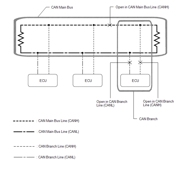
HINT:
- This waveform is measured between terminals CANH and GND, and terminals CANL and GND of the central gateway ECU (network gateway ECU). (Use this as a reference for diagnosis of CAN communication lines.)
- When malfunctions in multiple ECUs are suspected based on the CAN bus check and DTCs checked using the GTS, check the resistance of the CAN bus using an ohmmeter first. If no problems are found, check the following waveforms.
- If a waveform is not similar to one of the following 3 patterns (Group 1), then an open in a CAN main bus line, an open in a CAN branch line, or a short between a CAN line (CANH or CANL) and ground is suspected (Group 2).
- Wiggle the connector and wire harness to check if the waveform changes.
(a) CAN bus waveforms (Group 1)
(1) Normal waveform
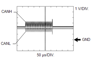
(2) Open in both of the lines (CANH and CANL) of a CAN branch
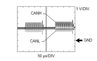
HINT:
- Waveforms (waveforms shown using dotted lines) are not output from an ECU or sensor connected to a CAN branch with an open circuit in both lines. (Waveforms from other ECUs or sensors are normal.)
- Because this waveform is similar to a normal waveform, instead of using the waveform, the malfunctioning part can be narrowed down by performing a CAN bus check.
(3) Short between the CAN bus lines (CANH and CANL)
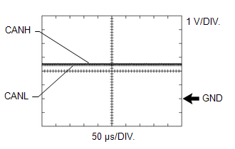
HINT:
- Waveforms disappear.
- If the malfunction is in an ECU, disconnecting the ECU will change the waveform. If the waveform does not change, a malfunction in the wire harness is suspected.
(b) CAN bus waveforms (reference) (Group 2)
NOTICE:
The following CAN bus waveforms can be used only as reference. The actual measured waveform may differ significantly depending on the location of the open or short circuit.
(1) Open in a CAN branch line (CANH)
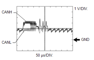
HINT:
- An abnormal waveform is output from an ECU with an open in one of its CAN branch lines. Because this abnormal output interferes with the signals from other ECUs, the output of other ECUs will also appear abnormal.
- Narrow down the malfunctioning part by checking DTCs or performing a CAN bus check, or by checking waveform changes when ECUs or sensors are disconnected. The waveform will change to one for an open in both sides of a CAN branch when the ECU or sensor with an open CAN branch line is disconnected.
(2) Open in a CAN branch line (CANL)
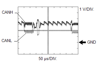
HINT:
- An abnormal waveform is output from an ECU with an open in one of its CAN branch lines. Because this abnormal output interferes with the signals from other ECUs, the output of other ECUs will also appear abnormal.
- Narrow down the malfunctioning part by checking DTCs or performing a CAN bus check, or by checking waveform changes when ECUs or sensors are disconnected. The waveform will change to one for an open in both sides of a CAN branch when the ECU or sensor with an open CAN branch line is disconnected.
(3) Open in a CAN main bus line (CANH)
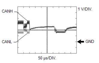
HINT:
- Waveforms of ECUs or sensors that are closer to the central gateway ECU (network gateway ECU) than the open part are almost normal.
- Waveforms of ECUs or sensors that are on the opposite side of the central gateway ECU (network gateway ECU) from the open part are abnormal.
- An open in a CAN main bus line can be confirmed by measuring the resistance between the CANH and CANL terminals of any CAN branch.
(4) Short between a CAN bus line (CANH) and ground
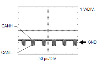
HINT:
- Narrow down the shorted part by checking for waveform changes when disconnecting connectors from the CAN junction connectors or when disconnecting ECUs or sensors.
- A short to ground in the CANH line can be confirmed by measuring the resistance between CANH and ground using an ohmmeter.
(5) Short between a CAN bus line (CANL) and ground
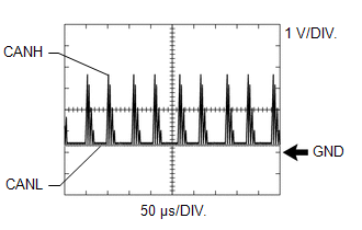
HINT:
- Narrow down the shorted part by checking for waveform changes when disconnecting connectors from the CAN junction connectors or when disconnecting ECUs or sensors.
- A short to ground in the CANL line can be confirmed by measuring the resistance between CANL and ground using an ohmmeter.
 Terminals Of Ecu
TERMINALS OF ECU NOTICE:
After turning the ignition switch off, waiting time may be required before disconnecting the cable from the negative (-) auxiliary battery terminal...
 Dtc Check / Clear
DTC CHECK / CLEAR CHECK FOR DTC (a) Read the DTCs. Body Electrical > Central Gateway > Trouble Codes CLEAR DTC (a) Read the DTCs. Body Electrical > Central Gateway > Trouble Codes (b) Clear the DTCs...
Other information:
Toyota Yaris XP210 (2020-2026) Reapir and Service Manual: High Mounted Stop Light Assembly
ComponentsCOMPONENTS ILLUSTRATION *1 CENTER STOP LIGHT ASSEMBLY - - RemovalREMOVAL PROCEDURE 1. REMOVE REAR SPOILER ASSEMBLY Click here 2. REMOVE CENTER STOP LIGHT ASSEMBLY (a) Remove the 2 screws to remove the center stop light assembly...
Toyota Yaris XP210 (2020-2026) Owner's Manual: Inside Trunk Release Lever
Your vehicle is equipped with an inside trunk release lever that provides a means of escape for children and adults in the event they become locked inside the trunk. No matter how careful adults might be with keys and locking their cars, parents should be aware that children may be tempted to play around vehicles and use the trunk as a hiding place...
Categories
- Manuals Home
- Toyota Yaris Owners Manual
- Toyota Yaris Service Manual
- Immobilizer System
- Fuel Gauge
- How to connect USB port/Auxiliary jack
- New on site
- Most important about car
Refueling
Before refueling, close all the doors, windows, and the liftgate/trunk lid, and switch the ignition OFF.
To open the fuel-filler lid, pull the remote fuel-filler lid release.
