Toyota Yaris: Lighting System / Headlight Dimmer Switch Circuit
DESCRIPTION
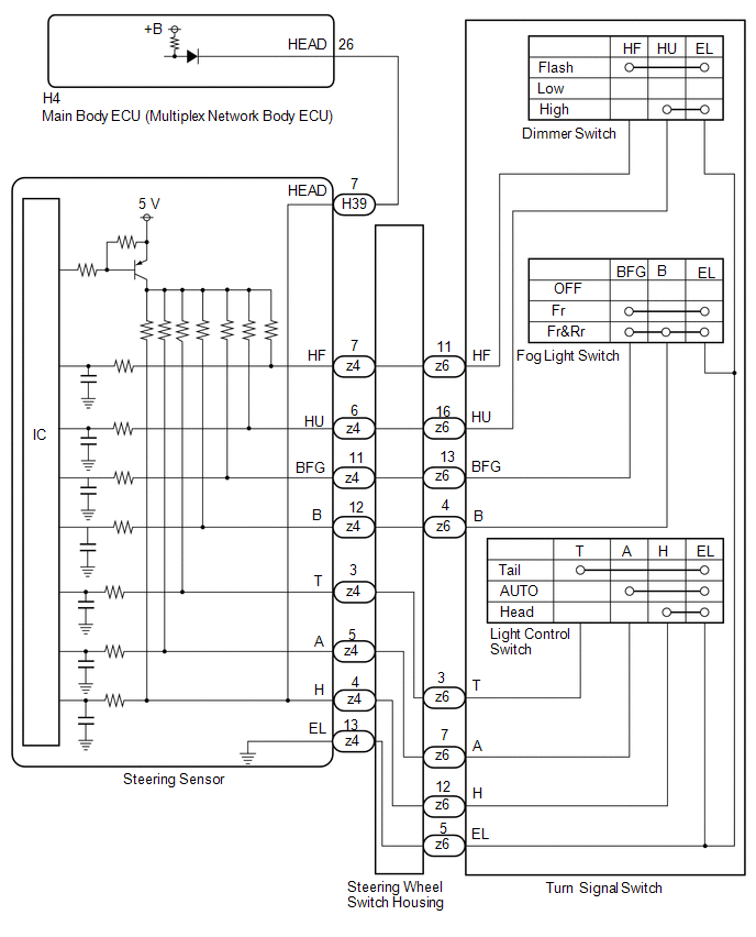
The steering sensor receives the following switch information:
- Light control switch in tail, head or AUTO position
- Dimmer switch in high, low or high flash (pass) position
- Fog light switch in front or off position
WIRING DIAGRAM
CAUTION / NOTICE / HINT
NOTICE:
Before replacing the main body ECU (multiplex network body ECU), refer to Registration.
Click here
.gif)
PROCEDURE
| 1. | READ VALUE USING GTS |
(a) Read the Data List according to the display on the GTS.
Chassis > Steering Angle Sensor > Data List| Tester Display | Measurement Item | Range | Normal Condition | Diagnostic Note |
|---|---|---|---|---|
| Light OFF Switch | Light control switch off position signal | OFF or ON | OFF: Light control switch not in off position ON: Light control switch in off position | - |
| Auto Light Switch | Light control switch AUTO position signal | OFF or ON | OFF: Light control switch not in AUTO position ON: Light control switch in AUTO position | - |
| Head Light Switch (Tail) | Light control switch tail position signal | OFF or ON | OFF: Light control switch in neither tail nor head position ON: Light control switch in tail or head position | - |
| Head Light Switch (Head) | Light control switch head position signal | OFF or ON | OFF: Light control switch not in head position ON: Light control switch in head position | - |
| High Beam Main Switch | Dimmer switch high position signal | OFF or ON | OFF: Dimmer switch not in high position ON: Dimmer switch in high position | - |
| Passing Light Switch | Dimmer switch high flash position (pass) signal | OFF or ON | OFF: Dimmer switch not in high flash position ON: Dimmer switch in high flash position | - |
| Front Fog Light Switch | Front fog light switch signal | OFF or ON | OFF: Front fog light switch off ON: Front fog light switch on | - |
| Rear Fog Light/Bad Weather Switch | Rear fog light switch signal | OFF or ON | OFF: Rear fog light switch off ON: Rear fog light switch on | - |
| Tester Display |
|---|
| Light OFF Switch |
| Auto Light Switch |
| Head Light Switch (Tail) |
| Head Light Switch (Head) |
| High Beam Main Switch |
| Passing Light Switch |
| Front Fog Light Switch |
| Rear Fog Light/Bad Weather Switch |
OK:
Normal conditions listed above are displayed.
| NG |
.gif) | GO TO STEP 8 |
|
.gif)
| 2. | READ VALUE USING GTS |
(a) Read the Data List according to the display on the GTS.
Body Electrical > Main Body > Data List| Tester Display | Measurement Item | Range | Diagnostic Note |
|---|---|---|---|
| Light Control Switch (HEAD) | Light control switch head position signal | OFF: Light control switch not in head position ON: Light control switch in head position | - |
| Tester Display | Measurement Item | Range | Diagnostic Note |
|---|---|---|---|
| Head Light Switch (Head) | Light control switch head position signal | OFF: Light control switch not in head position ON: Light control switch in head position | - |
| Tester Display |
|---|
| Light Control Switch (HEAD) |
| Tester Display |
|---|
| Head Light Switch (Head) |
OK:
Normal conditions listed above are displayed.
| Result | Proceed to |
|---|---|
| OK | A |
| NG ("Steering Angle Sensor" side abnormality) | B |
| NG ("Main Body" side abnormality) | C |
| NG ("Steering Angle Sensor" and "Main Body" are abnormality) | D |
| A |
| PROCEED TO NEXT SUSPECTED AREA SHOWN IN PROBLEM SYMPTOMS TABLE |
| B |
| REPLACE STEERING SENSOR |
| D |
| GO TO STEP 4 |
|
| 3. | CHECK HARNESS AND CONNECTOR (STEERING SENSOR - MAIN BODY ECU [MULTIPLEX NETWORK BODY ECU]) |
(a) Disconnect the H4 main body ECU (multiplex network body ECU) connector.
(b) Disconnect the H39 steering sensor connector.
(c) Measure the resistance according to the value(s) in the table below.
Standard Resistance:
| Tester Connection | Condition | Specified Condition |
|---|---|---|
| H4-26 (HEAD) - H39-7 (HEAD) | Always | Below 1 Ω |
| H4-26 (HEAD) or H39-7 (HEAD) - Body ground | Always | 10 kΩ or higher |
| OK |
| REPLACE MAIN BODY ECU (MULTIPLEX NETWORK BODY ECU) |
| NG |
| REPAIR OR REPLACE HARNESS OR CONNECTOR |
| 4. | INSPECT TURN SIGNAL SWITCH |
Click here
| NG |
| REPLACE TURN SIGNAL SWITCH |
|
| 5. | INSPECT STEERING WHEEL SWITCH HOUSING |
Click here
| NG |
| REPLACE STEERING WHEEL SWITCH HOUSING |
|
| 6. | CHECK HARNESS AND CONNECTOR (STEERING SENSOR - MAIN BODY ECU [MULTIPLEX NETWORK BODY ECU]) |
(a) Disconnect the H4 main body ECU (multiplex network body ECU) connector.
(b) Disconnect the H39 steering sensor connector.
(c) Measure the resistance according to the value(s) in the table below.
Standard Resistance:
| Tester Connection | Condition | Specified Condition |
|---|---|---|
| H4-26 (HEAD) - H39-7 (HEAD) | Always | Below 1 Ω |
| H4-26 (HEAD) or H39-7 (HEAD) - Body ground | Always | 10 kΩ or higher |
| NG |
| REPAIR OR REPLACE HARNESS OR CONNECTOR |
|
| 7. | READ VALUE USING GTS |
(a) Read the Data List according to the display on the GTS.
Body Electrical > Main Body > Data List| Tester Display | Measurement Item | Range | Normal Condition | Diagnostic Note |
|---|---|---|---|---|
| Light Control Switch (HEAD) | Light control switch head position signal | OFF or ON | OFF: Light control switch not in head position ON: Light control switch in head position | - |
| Tester Display |
|---|
| Light Control Switch (HEAD) |
OK:
Normal conditions listed above are displayed.
| OK |
| REPLACE MAIN BODY ECU (MULTIPLEX NETWORK BODY ECU) |
| NG |
| REPLACE STEERING SENSOR |
| 8. | INSPECT TURN SIGNAL SWITCH |
Click here
| NG |
| REPLACE TURN SIGNAL SWITCH |
|
| 9. | INSPECT STEERING WHEEL SWITCH HOUSING |
Click here
| OK |
| REPLACE STEERING SENSOR |
| NG |
| REPLACE STEERING WHEEL SWITCH HOUSING |
 Automatic High Beam System does not Operate or Operation Indicator does not Illuminate
DESCRIPTION The main body ECU (multiplex network body ECU) controls the automatic high beam system based on signals received from the forward recognition camera...
 Clearance Light/Daytime Running Light Circuit
DESCRIPTION
Clearance light function:
When the main body ECU (multiplex network body ECU) receives the light control switch position signal, it sends an illumination request signal to the light control LED ECU and illuminates the clearance lights...
Other information:
Toyota Yaris XP210 (2020-2026) Reapir and Service Manual: Removal
REMOVAL PROCEDURE 1. REMOVE DECK TRIM SIDE PANEL ASSEMBLY LH Click here 2. REMOVE RADIO SETTING CONDENSER NOTICE: When the terminal cover is removed, the radio setting condenser must be replaced because the terminal cover and condenser are supplied as a set...
Toyota Yaris XP210 (2020-2026) Reapir and Service Manual: Installation
INSTALLATION PROCEDURE 1. INSTALL TIMING CHAIN COVER OIL SEAL Click here 2. INSTALL TIMING CHAIN COVER ASSEMBLY (a) Install 2 new O-rings to the cylinder block sub-assembly. (b) Clean the contact surfaces of the timing chain cover assembly, oil pan sub-assembly and cylinder block sub-assembly, and confirm that no oil, moisture, or other foreign matter is on the surfaces...
Categories
- Manuals Home
- Toyota Yaris Owners Manual
- Toyota Yaris Service Manual
- Headlights
- Adjustment
- Maintenance
- New on site
- Most important about car
Refueling
Before refueling, close all the doors, windows, and the liftgate/trunk lid, and switch the ignition OFF.
To open the fuel-filler lid, pull the remote fuel-filler lid release.
