Toyota Yaris: Lighting System / Clearance Light/Daytime Running Light Circuit
DESCRIPTION
-
Clearance light function:
When the main body ECU (multiplex network body ECU) receives the light control switch position signal, it sends an illumination request signal to the light control LED ECU and illuminates the clearance lights.
-
Daytime running light function:
When the operation conditions of the daytime running lights are met, the main body ECU (multiplex network body ECU) sends an illumination request signal to the light control LED ECU and illuminates the daytime running lights.
WIRING DIAGRAM
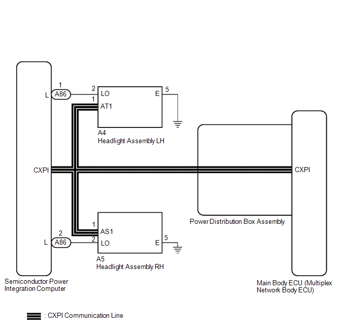
HEADLIGHT ASSEMBLY CIRCUIT
CAUTION / NOTICE / HINT
NOTICE:
- Inspect the fuses for circuits related to this system before performing the following procedure.
-
Before replacing the main body ECU (multiplex network body ECU), refer to Registration.
Click here
.gif)
-
First perform the communication function inspections in How to Proceed with Troubleshooting to confirm that there are no CAN communication malfunctions before troubleshooting this symptom.
Click here
-
First perform the communication function inspections in How to Proceed with Troubleshooting to confirm that there are no CXPI communication malfunctions before troubleshooting this symptom.
Click here
PROCEDURE
| 1. | PERFORM ACTIVE TEST USING GTS |
(a) Using the GTS, perform the Active Test.
Body Electrical > Main Body > Active Test| Tester Display | Measurement Item | Control Range | Diagnostic Note |
|---|---|---|---|
| Daytime Running Light | Daytime running lights | OFF or ON | - |
| Tester Display |
|---|
| Daytime Running Light |
OK:
Clearance lights and daytime running lights illuminate.
| Result | Proceed to |
|---|---|
| OK | A |
| NG (LH side clearance light and daytime running light does not illuminate.) | B |
| NG (RH side clearance light and daytime running light does not illuminate.) | C |
| A |
.gif) | PROCEED TO NEXT SUSPECTED AREA SHOWN IN PROBLEM SYMPTOMS TABLE |
| C |
| GO TO STEP 7 |
|
.gif)
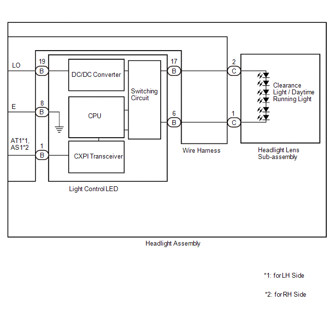
| 2. | INSPECT HEADLIGHT ASSEMBLY LH (LO TERMINAL VOLTAGE) |
(a) Disconnect the A4 headlight unit assembly LH connector.
(b) Measure the voltage according to the value(s) in the table below.
Standard Voltage:
| Tester Connection | Switch Condition | Specified Condition |
|---|---|---|
| A4-2 (LO) - Body ground | Always | Below 1 Ω |
| NG |
| REPAIR OR REPLACE HARNESS OR CONNECTOR |
|
| 3. | CHECK HARNESS AND CONNECTOR (HEADLIGHT ASSEMBLY LH - BODY GROUND) |
(a) Measure the resistance according to the value(s) in the table below.
Standard Resistance:
| Tester Connection | Condition | Specified Condition |
|---|---|---|
| A4-5 (E) - Body ground | Always | Below 1 Ω |
| NG |
| REPAIR OR REPLACE HARNESS OR CONNECTOR |
|
| 4. | CHECK HARNESS AND CONNECTOR (HEADLIGHT LENS SUB-ASSEMBLY LH - LIGHT CONTROL LED ECU LH) |

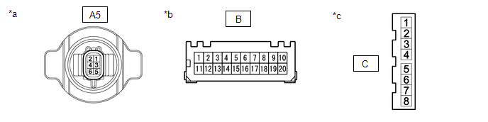
| *a | Component without harness connected (to Wire Harness) | *b | Component without harness connected (to Light Control LED ECU) |
| *c | Component without harness connected (to Headlight Lens Sub-assembly LH) | - | - |
(a) Remove the headlight assembly LH.
Click here
(b) Remove the wire harness.
Click here
(c) Measure the resistance according to the value(s) in the table below.
Standard Resistance:
| Tester Connection | Condition | Specified Condition |
|---|---|---|
| B-[17] - C-[2] | Always | Below 1 Ω |
| B-[6] - C-[1] | Always | Below 1 Ω |
| A4-2 (LO) - B-[19] | Always | Below 1 Ω |
| A4-5 (E) - B-[8] | Always | Below 1 Ω |
| NG |
| REPLACE HARNESS OR CONNECTOR |
|
| 5. | CHECK LIGHT CONTROL LED ECU LH |
(a) Interchange the light control LED ECU LH with RH and connect the connectors to them.
Click here
|
| 6. | CHECK OPERATION (DAYTIME RUNNING LIGHT) |
(a) Check that the daytime running light operates normally.
OK:
Daytime running light operates normally.
| OK |
| REPLACE LIGHT CONTROL LED ECU LH |
| NG |
| REPLACE HEADLIGHT LENS SUB-ASSEMBLY |
| 7. | INSPECT HEADLIGHT ASSEMBLY RH (LO TERMINAL VOLTAGE) |
(a) Disconnect the A5 headlight assembly RH connector.
(b) Measure the voltage according to the value(s) in the table below.
Standard Voltage:
| Tester Connection | Switch Condition | Specified Condition |
|---|---|---|
| A5-2 (LO) - Body ground | Always | 11 to 14 V |
| NG |
| REPAIR OR REPLACE HARNESS OR CONNECTOR |
|
| 8. | CHECK HARNESS AND CONNECTOR (HEADLIGHT ASSEMBLY RH - BODY GROUND) |
(a) Measure the resistance according to the value(s) in the table below.
Standard Resistance:
| Tester Connection | Condition | Specified Condition |
|---|---|---|
| A5-5 (E) - Body ground | Always | Below 1 Ω |
| NG |
| REPAIR OR REPLACE HARNESS OR CONNECTOR |
|
| 9. | CHECK HARNESS AND CONNECTOR (HEADLIGHT LENS SUB-ASSEMBLY RH - LIGHT CONTROL LED ECU RH) |
| *a | Component without harness connected (to Wire Harness) | *b | Component without harness connected (to Light Control LED ECU) |
| *c | Component without harness connected (to Headlight Lens Sub-assembly RH) | - | - |
(a) Remove the headlight assembly RH.
Click here
(b) Remove the wire harness.
Click here
(c) Measure the resistance according to the value(s) in the table below.
Standard Resistance:
| Tester Connection | Condition | Specified Condition |
|---|---|---|
| B-[17] - C-[2] | Always | Below 1 Ω |
| B-[6] - C-[1] | Always | Below 1 Ω |
| A5-2 (LO) - B-[19] | Always | Below 1 Ω |
| A5-5 (E) - B-[8] | Always | Below 1 Ω |
| NG |
| REPLACE HARNESS OR CONNECTOR |
|
| 10. | CHECK LIGHT CONTROL LED ECU RH |
(a) Interchange the headlight unit assembly RH with LH and connect the connectors to them.
Click here
|
| 11. | CHECK OPERATION (DAYTIME RUNNING LIGHT) |
(a) Check that the daytime running light operates normally.
OK:
Daytime running light operates normally.
| OK |
| REPLACE LIGHT CONTROL LED ECU RH |
| NG |
| REPLACE HEADLIGHT LENS SUB-ASSEMBLY |
 Headlight Dimmer Switch Circuit
DESCRIPTION The steering sensor receives the following switch information:
Light control switch in tail, head or AUTO position
Dimmer switch in high, low or high flash (pass) position
Fog light switch in front or off position
WIRING DIAGRAM
CAUTION / NOTICE / HINT NOTICE: Before replacing the main body ECU (multiplex network body ECU), refer to Registration...
 Front Fog Light Circuit
DESCRIPTION The main body ECU (multiplex network body ECU) controls the front fog lights. WIRING DIAGRAM
CAUTION / NOTICE / HINT NOTICE:
Before replacing the main body ECU (multiplex network body ECU), refer to Registration...
Other information:
Toyota Yaris XP210 (2020-2026) Reapir and Service Manual: Installation
INSTALLATION PROCEDURE 1. INSTALL ENGINE COOLANT TEMPERATURE SENSOR HINT: Perform "Inspection After Repair" after replacing the engine coolant temperature sensor. Click here (a) Apply a light coat of engine coolant to the O-ring of the engine coolant temperature sensor...
Toyota Yaris XP210 (2020-2026) Reapir and Service Manual: Installation
INSTALLATION PROCEDURE 1. INSTALL MAIN BODY ECU (MULTIPLEX NETWORK BODY ECU) NOTICE: Make sure that the connecting surfaces are free of foreign matter. Do not touch the main body ECU (multiplex network body ECU) connector. (a) Set the main body ECU (multiplex network body ECU) to the position where the guide of the main body ECU (multiplex network body ECU) contacts the housing sidewall of the power distribution box assembly as shown in the illustration...
Categories
- Manuals Home
- Toyota Yaris Owners Manual
- Toyota Yaris Service Manual
- Maintenance
- Diagnostic Trouble Code Chart
- To Set Speed
- New on site
- Most important about car
Key Suspend Function
If a key is left in the vehicle, the functions of the key left in the vehicle are temporarily suspended to prevent theft of the vehicle.
To restore the functions, press the unlock button on the functions-suspended key in the vehicle.