Toyota Yaris: Fuel Pump (for High Pressure) / Removal
REMOVAL
CAUTION / NOTICE / HINT
The necessary procedures (adjustment, calibration, initialization or registration) that must be performed after parts are removed and installed, or replaced during fuel pump assembly removal/installation are shown below.
Necessary Procedures After Parts Removed/Installed/Replaced| Replaced Part or Performed Procedure | Necessary Procedure | Effect/Inoperative Function when Necessary Procedure not Performed | Link |
|---|---|---|---|
| Fuel pump assembly (for high pressure side) | Inspection after repair |
|
|

CAUTION:
-
Never perform work on fuel system components near any possible ignition sources.
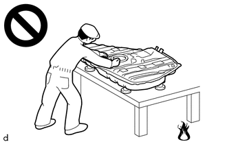
- Vaporized fuel could ignite, resulting in a serious accident.
-
Do not perform work on fuel system components without first disconnecting the cable from the negative (-) auxiliary battery terminal.
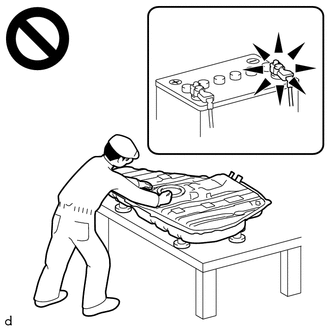
- Sparks could cause vaporized fuel to ignite, resulting in a serious accident.
NOTICE:
- After the ignition switch is turned off, the radio and display receiver assembly records various types of memory and settings. As a result, after turning the ignition switch off, make sure to wait at least 120 seconds before disconnecting the cable from the negative (-) auxiliary battery terminal.
-
This procedure includes the removal of small-head bolts. Refer to Small-Head Bolts of Basic Repair Hint to identify the small-head bolts.
Click here

HINT:
When the cable is disconnected/reconnected to the auxiliary battery terminal, systems temporarily stop operating. However, each system has a function that completes learning the first time the system is used.
-
Learning completes when vehicle is driven
Effect/Inoperative Function When Necessary Procedures are not Performed
Necessary Procedures
Link
Lane tracing assist system
Drive the vehicle straight ahead at 35 km/h (22 mph) or more for 5 second or more.

Pre-collision system
Stop and start system
Drive the vehicle until stop and start control is permitted (approximately 5 to 60 minutes)

-
Learning completes when vehicle is operated normally
Effect/Inoperative Function When Necessary Procedures are not Performed
Necessary Procedures
Link
Power door lock control system
- Back door opener
Perform door unlock operation with door control switch or electrical key transmitter sub-assembly switch.

Air conditioning system
After the ignition switch is turned to ON, the servo motor standard position is recognized.
-
PROCEDURE
1. DISCHARGE FUEL SYSTEM PRESSURE
Click here

2. PRECAUTION
NOTICE:
After turning the ignition switch off, waiting time may be required before disconnecting the cable from the negative (-) auxiliary battery terminal.
Click here

3. DISCONNECT CABLE FROM NEGATIVE AUXILIARY BATTERY TERMINAL
Click here

4. REMOVE WINDSHIELD WIPER MOTOR AND LINK ASSEMBLY
Click here

5. REMOVE FRONT NO. 1 VENTILATOR SEAL
Click here

6. REMOVE WATER GUARD PLATE RH
Click here

7. REMOVE OUTER COWL TOP PANEL SUB-ASSEMBLY
Click here

8. REMOVE NO. 1 ENGINE COVER SUB-ASSEMBLY
Click here

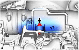
9. REMOVE NO. 1 VACUUM SWITCHING VALVE ASSEMBLY
Click here

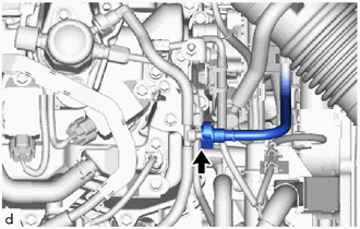
10. DISCONNECT NO. 1 FUEL TUBE SUB-ASSEMBLY
| (a) Disconnect the No. 1 fuel tube sub-assembly from the No. 2 fuel tube sub-assembly. Click here
|
|

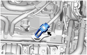
11. REMOVE FUEL PIPE CLAMP
| (a) Remove the fuel pipe clamp from the No. 2 fuel tube sub-assembly. |
|
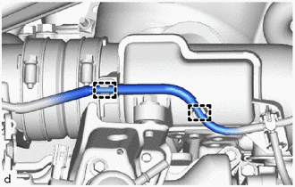
12. REMOVE NO. 2 FUEL TUBE SUB-ASSEMBLY
| (a) Remove the bolt. |
|
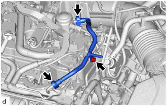
(b) Remove the No. 2 fuel tube sub-assembly from the fuel delivery pipe sub-assembly and fuel pump assembly.
Click here

13. DISCONNECT NO. 8 WATER BY-PASS HOSE
| (a) Slide the clip and disconnect the No. 8 water by-pass hose. |
|
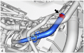
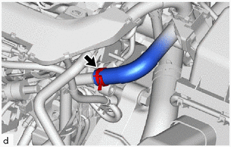
14. DISCONNECT NO. 1 WATER BY-PASS HOSE
| (a) Slide the clip and disconnect the No. 1 water by-pass hose. |
|
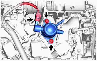
15. REMOVE NO. 1 FUEL PIPE SUB-ASSEMBLY
| (a) Using a 17 mm union nut wrench, loosen the 2 union nuts of the No. 1 fuel pipe sub-assembly. |
|
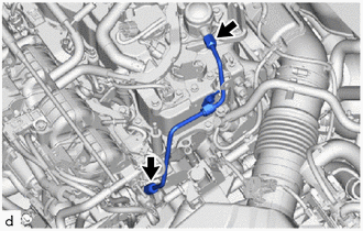
| (b) Remove the bolt. |
|
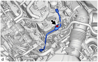
| (c) Using an 8 mm socket wrench, loosen the 2 bolts of the fuel pump assembly. |
|
(d) Remove the No. 1 fuel pipe sub-assembly from the fuel delivery pipe and fuel pump assembly.
16. DISCONNECT ENGINE WIRE
| (a) Disconnect the 2 connectors. |
|
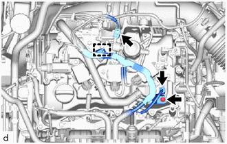
(b) Remove the bolt.
(c) Disengage the clamp and disconnect the engine wire.
17. DISCONNECT NO. 1 VACUUM TRANSMITTING HOSE
| (a) Disengage the 2 clamps and disconnect the No. 1 vacuum transmitting hose. |
|
18. SEPARATE INTAKE AIR RESONATOR
| (a) Remove the bolt and separate the intake air resonator from the fuel pump flange. |
|
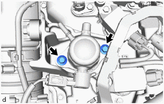
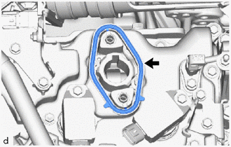
19. REMOVE FUEL PUMP ASSEMBLY
NOTICE:
When replacing the fuel pump assembly, it is necessary to replace the No. 1 fuel pipe sub-assembly with a new one.
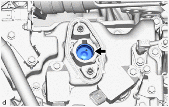
| (a) Remove the 2 bolts, fuel pump assembly and fuel pump flange from the cylinder head cover sub-assembly. |
|
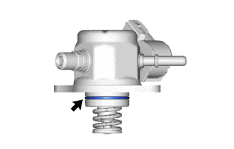
| (b) Remove the O-ring from the fuel pump assembly. |
|
| (c) Remove the fuel pump lifter assembly from the fuel pump lifter guide. |
|
| (d) Remove the fuel pump spacer gasket from the cylinder head cover sub-assembly. |
|
 On-vehicle Inspection
ON-VEHICLE INSPECTION PROCEDURE 1. FUEL PUMP ASSEMBLY OPERATION (a) Check fuel pressure. (1) Connect the GTS to the DLC3. (2) Turn the ignition switch to ON...
 Inspection
INSPECTION PROCEDURE 1. INSPECT FUEL PUMP ASSEMBLY (a) Measure the resistance according to the value(s) in the table below. Standard Resistance: Tester Connection Condition Specified Condition D24-1 - D24-2 20°C (68°F) 0...
Other information:
Toyota Yaris XP210 (2020-2026) Reapir and Service Manual: Fuel Tank Cap
I..
Toyota Yaris XP210 (2020-2026) Reapir and Service Manual: EPS Warning Light Circuit
DESCRIPTION Use the following procedure if no DTCs are output but the EPS warning light is illuminated continuously. The power steering ECU assembly controls the warning light in the combination meter assembly via CAN communication. CAUTION / NOTICE / HINT NOTICE: When the power steering ECU assembly has been replaced, perform Power Steering ECU Initial Setting (assist map writing)...
Categories
- Manuals Home
- Toyota Yaris Owners Manual
- Toyota Yaris Service Manual
- Engine Start Function When Key Battery is Dead
- Key Battery Replacement
- Power Integration No.1 System Missing Message (B235287,B235587,B235787-B235987)
- New on site
- Most important about car
Turning the Engine Off
Stop the vehicle completely. Manual transaxle: Shift into neutral and set the parking brake.Automatic transaxle: Shift the selector lever to the P position and set the parking brake.
Press the push button start to turn off the engine. The ignition position is off.