Toyota Yaris: Front Axle Hub / Removal
REMOVAL
CAUTION / NOTICE / HINT
The necessary procedures (adjustment, calibration, initialization, or registration) that must be performed after parts are removed and installed, or replaced during the front axle hub sub-assembly removal/installation are shown below.
Necessary Procedures After Parts Removed/Installed/Replaced| Replacement Part or Procedure | Necessary Procedures | Effect/Inoperative Function When Necessary Procedures are not Performed | Link |
|---|---|---|---|
| Front wheel alignment adjustment | ECU Data Initialization | Active torque split AWD system |
|
| Calibration |
|
|


HINT:
- Use the same procedure for the RH and LH sides.
- The following procedure is for the LH side.
PROCEDURE
1. REMOVE FRONT WHEEL
Click here

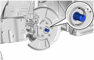
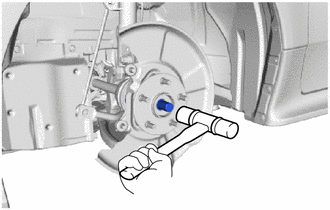
2. REMOVE FRONT AXLE SHAFT NUT
Click here

3. SEPARATE FRONT SPEED SENSOR
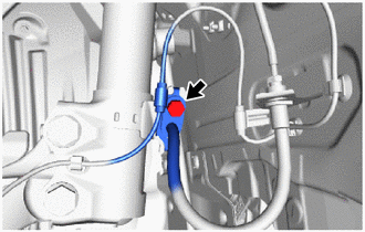
| (a) Remove the bolt and separate the front speed sensor and front flexible hose from the front shock absorber assembly. NOTICE: Be sure to separate the front speed sensor and front flexible hose from the front shock absorber assembly completely. |
|
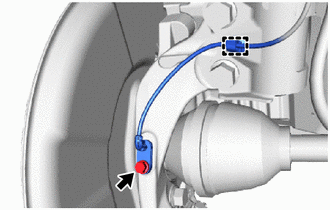
| (b) Remove the bolt, disengage the clamp and separate the front speed sensor from the front shock absorber assembly and steering knuckle. NOTICE:
|
|
4. SEPARATE TIE ROD END SUB-ASSEMBLY
Click here

5. SEPARATE FRONT DISC BRAKE CALIPER ASSEMBLY
Click here

6. REMOVE FRONT DISC
Click here

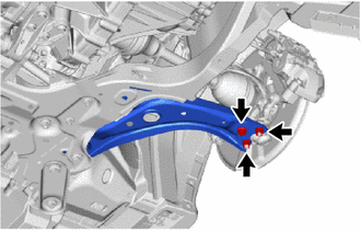
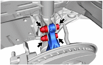
7. SEPARATE FRONT LOWER NO. 1 SUSPENSION ARM SUB-ASSEMBLY
| (a) Remove the bolt and 2 nuts and separate the front lower No. 1 suspension arm sub-assembly from the front lower ball joint assembly. |
|
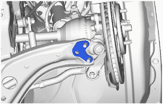
| (b) Remove inner No. 1 arm attachment plate from the front lower No. 1 suspension arm sub-assembly. |
|
8. SEPARATE FRONT DRIVE SHAFT ASSEMBLY
| (a) Put matchmarks on the front drive shaft assembly and the front axle hub sub-assembly. |
|
| (b) Using a plastic hammer, separate the front drive shaft assembly from the front axle assembly. NOTICE:
HINT: If it is difficult to separate the front drive shaft assembly from the front axle assembly, tap the end of the front drive shaft assembly using a brass bar and a hammer. |
|
9. REMOVE FRONT AXLE ASSEMBLY
| (a) Remove the 2 bolts, 2 nuts and front axle assembly from the front shock absorber assembly. NOTICE: When removing the nuts, keep the bolts from rotating. |
|
10. REMOVE FRONT AXLE HUB SUB-ASSEMBLY
| (a) Secure the front axle assembly between aluminum plates in a vise. NOTICE: Do not overtighten the vise. |
|
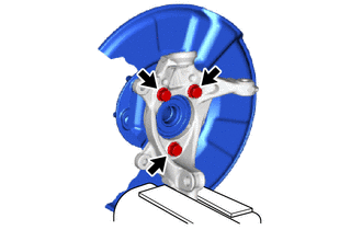
(b) Remove the 3 bolts, front axle hub sub-assembly and front disc brake dust cover from the steering knuckle.
NOTICE:
- Do not drop the front axle hub sub-assembly.
- Be careful not to damage the speed sensor rotor or contact surfaces.
- Do not allow foreign matter to contact the speed sensor rotor or contact surfaces.
 On-vehicle Inspection
ON-VEHICLE INSPECTION CAUTION / NOTICE / HINT HINT:
The following procedure is for the LH side.
Use the same procedure for the RH side and LH side...
 Installation
INSTALLATION CAUTION / NOTICE / HINT HINT:
Use the same procedure for the RH side and LH side.
The following procedure is for the LH side.
PROCEDURE 1...
Other information:
Toyota Yaris XP210 (2020-2026) Reapir and Service Manual: Disassembly
DISASSEMBLY PROCEDURE 1. REMOVE BRAKE VACUUM CHECK VALVE ASSEMBLY (a) Remove the brake vacuum check valve assembly from the brake booster assembly. (b) Remove the check valve grommet from the brake booster assembly. 2. REMOVE VACUUM SENSOR ASSEMBLY (a) Remove the vacuum sensor assembly from the brake booster assembly...
Toyota Yaris XP210 (2020-2026) Reapir and Service Manual: Control Module Performance Bank 1 Watchdog/Safety MCU Failure (P060747,P060787)
MONITOR DESCRIPTION The ECM continuously monitors its internal ICs and the monitor IC. If the monitor IC is abnormal, the ECM illuminates the MIL and stores DTC P060747. If an internal IC is abnormal, the ECM illuminates the MIL and stores DTC P060787...
Categories
- Manuals Home
- Toyota Yaris Owners Manual
- Toyota Yaris Service Manual
- Adjustment
- How to connect USB port/Auxiliary jack
- Removal
- New on site
- Most important about car
Fuel Gauge
The fuel gauge shows approximately how much fuel is remaining in the tank when the ignition is switched ON. We recommend keeping the tank over 1/4 full.
