Toyota Yaris: Front Axle Hub / Installation
INSTALLATION
CAUTION / NOTICE / HINT
HINT:
- Use the same procedure for the RH side and LH side.
- The following procedure is for the LH side.
PROCEDURE
1. INSTALL FRONT AXLE HUB SUB-ASSEMBLY
(a) Secure the steering knuckle between aluminum plates in a vise.
NOTICE:
Do not overtighten the vise.
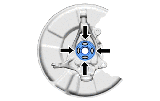
(b) Install the front axle hub sub-assembly and front disc brake dust cover to the steering knuckle with the 3 bolts.
Torque:
130 N·m {1326 kgf·cm, 96 ft·lbf}
NOTICE:
- Be careful not to damage the speed sensor rotor or contact surfaces.
- Do not allow foreign matter to contact the speed sensor rotor or contact surfaces.
2. INSTALL FRONT AXLE ASSEMBLY
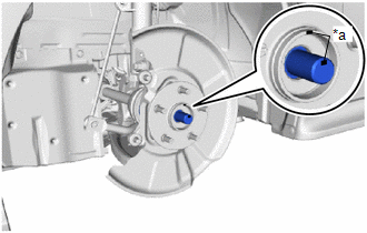
(a) Apply 0.1 to 0.3 g (0.00353 to 0.0105 oz.) of Toyota Body Grease W to each of the 4 areas shown in the illustration.
 | Toyota Body Grease W |
(b) Install the front axle assembly to the front shock absorber assembly with the 2 bolts and 2 nuts.
Torque:
270 N·m {2753 kgf·cm, 199 ft·lbf}
NOTICE:
- Do not apply lubricants to the steering knuckle and shock absorber contact surfaces.
- When installing the nuts, keep the bolts from rotating.
HINT:
The bolts can be installed in either direction, however, make sure that they are both installed in the same direction.
3. INSTALL FRONT DRIVE SHAFT ASSEMBLY
| (a) Align the matchmarks on the front drive shaft assembly and front axle hub sub-assembly, and connect the front drive shaft assembly to the front axle assembly. NOTICE:
|
|
4. CONNECT FRONT LOWER NO. 1 SUSPENSION ARM SUB-ASSEMBLY
(a) Connect the front lower No. 1 suspension arm sub-assembly and inner No. 1 arm attachment plate to the front lower ball joint assembly with the bolt and 2 nuts.
Torque:
89 N·m {908 kgf·cm, 66 ft·lbf}
5. CONNECT TIE ROD END SUB-ASSEMBLY
Click here

6. INSTALL FRONT DISC
Click here

7. INSTALL FRONT DISC BRAKE CALIPER ASSEMBLY
Click here

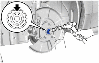
8. INSTALL FRONT AXLE SHAFT NUT
(a) Clean the threaded parts on the front drive shaft assembly and a new front axle shaft nut using non-residue solvent.
NOTICE:
- Be sure to perform this work even when using a new front drive shaft assembly.
- Keep the threaded parts free of oil and foreign matter.
(b) Using a 30 mm deep socket wrench, while applying the brakes, temporarily install the front axle shaft nut.
Torque:
294 N·m {2998 kgf·cm, 217 ft·lbf}
NOTICE:
Stake the front axle shaft nut after inspecting for looseness and runout in the following steps.
HINT:
Keep depressing the brake pedal to prevent the front drive shaft from rotating.
9. SEPARATE FRONT DISC BRAKE CALIPER ASSEMBLY
Click here

10. REMOVE FRONT DISC
Click here

11. INSPECT FRONT AXLE HUB BEARING LOOSENESS
Click here

12. INSPECT FRONT AXLE HUB RUNOUT
Click here

13. INSTALL FRONT DISC
Click here

14. INSTALL FRONT DISC BRAKE CALIPER ASSEMBLY
Click here

15. INSTALL FRONT SPEED SENSOR
(a) Set the 2 hooks of the front speed sensor to the front shock absorber assembly.
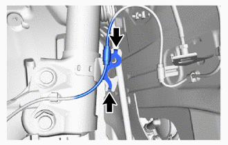
 | Hook |
NOTICE:
Do not twist the front speed sensor when installing it.
| (b) Install the front speed sensor and front flexible hose to the front shock absorber assembly with the bolt. Torque: 29.4 N·m {300 kgf·cm, 22 ft·lbf} NOTICE: Do not twist the front flexible hose when installing it. |
|
| (c) Install the front speed sensor to the steering knuckle with the bolt. Torque: 8.5 N·m {87 kgf·cm, 75 in·lbf} NOTICE:
|
|
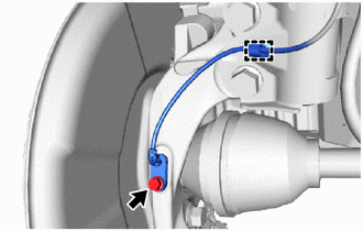
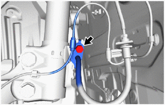
(d) Engage the clamp.
NOTICE:
Do not twist the front speed sensor when installing it.
16. STAKE FRONT AXLE SHAFT NUT
| (a) Using a chisel and hammer, stake the front axle shaft nut. |
|
17. INSTALL FRONT WHEEL
Click here

18. INSPECT AND ADJUST FRONT WHEEL ALIGNMENT
Click here

19. CHECK FOR SPEED SENSOR SIGNAL
Click here

 Removal
REMOVAL CAUTION / NOTICE / HINT The necessary procedures (adjustment, calibration, initialization, or registration) that must be performed after parts are removed and installed, or replaced during the front axle hub sub-assembly removal/installation are shown below...
 Front Axle Hub Bolt
ComponentsCOMPONENTS ILLUSTRATION
*1 FRONT AXLE HUB BOLT *2 FRONT DISC *3 FRONT DISC BRAKE CALIPER ASSEMBLY - -
Tightening torque for "Major areas involving basic vehicle performance such as moving/turning/stopping": N*m (kgf*cm, ft...
Other information:
Toyota Yaris XP210 (2020-2026) Reapir and Service Manual: Door Control Receiver
ComponentsCOMPONENTS ILLUSTRATION *1 DOOR CONTROL RECEIVER - - N*m (kgf*cm, ft.*lbf): Specified torque - - RemovalREMOVAL PROCEDURE 1. REMOVE DECK TRIM SIDE PANEL ASSEMBLY Click here 2. REMOVE DOOR CONTROL RECEIVER NOTICE: Do not drop, strike or otherwise subject the door control receiver to impact...
Toyota Yaris XP210 (2020-2026) Owner's Manual: Driving on Uneven Road
Your vehicle’s suspension and underbody can be damaged if driven on rough/uneven roads or over speed bumps at excessive speeds. Use care and reduce speed when traveling on rough/uneven roads or over speed bumps. Use care not to damage the vehicle’s underbody, bumpers or muffler(s) when driving under the following conditions: Ascending or descending a slope with a sharp transition angle Ascending or descending a driveway or trailer ramp with a sharp transition angle NOTICE This vehicle is equipped with low profile tires allowing class-leading performance and handling...
Categories
- Manuals Home
- Toyota Yaris Owners Manual
- Toyota Yaris Service Manual
- To Set Speed
- Opening and Closing the Liftgate/Trunk Lid
- Immobilizer System
- New on site
- Most important about car
Break-In Period
No special break-in is necessary, but a few precautions in the first 600 miles (1,000 km) may add to the performance, economy, and life of the vehicle.
Do not race the engine. Do not maintain one constant speed, either slow or fast, for a long period of time. Do not drive constantly at full-throttle or high engine rpm for extended periods of time. Avoid unnecessary hard stops. Avoid full-throttle starts.