Toyota Yaris: Axle And Differential / Front Axle Hub Bolt
Components
COMPONENTS
ILLUSTRATION
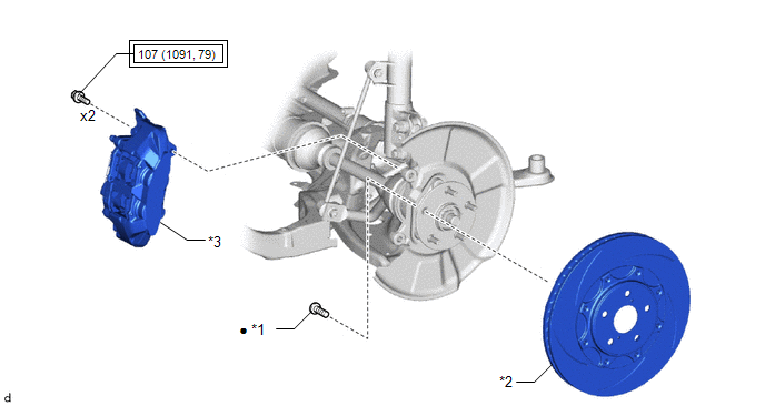
| *1 | FRONT AXLE HUB BOLT | *2 | FRONT DISC |
| *3 | FRONT DISC BRAKE CALIPER ASSEMBLY | - | - |
 | Tightening torque for "Major areas involving basic vehicle performance such as moving/turning/stopping": N*m (kgf*cm, ft.*lbf) | ● | Non-reusable part |
Replacement
REPLACEMENT
CAUTION / NOTICE / HINT
HINT:
- Use the same procedure for the RH side and LH side.
- The following procedure is for the LH side.
PROCEDURE
1. REMOVE FRONT WHEEL
Click here

2. SEPARATE FRONT DISC BRAKE CALIPER ASSEMBLY
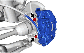
| (a) Remove the 2 bolts and separate the front disc brake caliper assembly from the steering knuckle. NOTICE: Use wire or an equivalent tool to keep the front disc brake caliper assembly from hanging by the front flexible hose. |
|
3. REMOVE FRONT DISC
Click here

4. REMOVE FRONT AXLE HUB BOLT
(a) Temporarily install 2 service nuts to the front axle hub bolts as shown in the illustration.
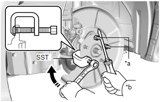
| *a | Service Nut |
| *b | Hold |
 | Turn |
Recommended Service Nut:
Thread diameter: 12.0 mm (0.472 in.)
Thread pitch: 1.5 mm (0.0591 in.)
NOTICE:
Install the service nuts to prevent damage to the front axle hub bolts.
(b) Using SST and a screwdriver or an equivalent tool to hold the front axle hub sub-assembly, remove the front axle hub bolt.
SST: 09611-12010
NOTICE:
Do not damage the threads of the front axle hub bolts.
5. INSTALL FRONT AXLE HUB BOLT
(a) Temporarily install a new front axle hub bolt to the front axle hub sub-assembly.
(b) Install a washer and service nut to the front axle hub bolt as shown in the illustration.
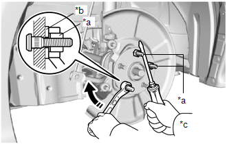
| *a | Service Nut |
| *b | Washer |
| *c | Hold |
 | Turn |
Recommended Service Nut:
Thread diameter: 12.0 mm (0.472 in.)
Thread pitch: 1.5 mm (0.0591 in.)
HINT:
Recommended washer thickness is 5 mm (0.197 in.) or more.
(c) Using a screwdriver or an equivalent tool to hold the front axle hub sub-assembly, install the front axle hub bolt by tightening the service nut.
NOTICE:
- Install the service nuts to prevent damage to the front axle hub bolts.
- Do not damage the threads of the front axle hub bolts.
(d) Remove the 3 service nuts and washer from the 3 front axle hub bolts.
6. INSTALL FRONT DISC
Click here

7. INSTALL FRONT DISC BRAKE CALIPER ASSEMBLY
(a) Install the front disc brake caliper assembly to the steering knuckle with the 2 bolts.
Torque:
107 N·m {1091 kgf·cm, 79 ft·lbf}
NOTICE:
- Do not twist the front flexible hose when installing the front disc brake caliper assembly.
- Make sure that there is no foreign matter on the threads of the bolt.
8. INSTALL FRONT WHEEL
Click here

 Installation
INSTALLATION CAUTION / NOTICE / HINT HINT:
Use the same procedure for the RH side and LH side.
The following procedure is for the LH side.
PROCEDURE 1...

Other information:
Toyota Yaris XP210 (2020-2026) Reapir and Service Manual: How To Proceed With Troubleshooting
CAUTION / NOTICE / HINT HINT: Use the following procedure to troubleshoot the power mirror control system. *: Use the GTS. PROCEDURE 1. VEHICLE BROUGHT TO WORKSHOP NEXT 2. CUSTOMER PROBLEM ANALYSIS HINT: In troubleshooting, confirm that the problem symptoms have been accurately identified...
Toyota Yaris XP210 (2020-2026) Reapir and Service Manual: Transfer Case Front Oil Seal (for Rh Side)
ComponentsCOMPONENTS ILLUSTRATION *1 DRIVE SHAFT BEARING BRACKET *2 TRANSFER CASE OIL SEAL RH Tightening torque for "Major areas involving basic vehicle performance such as moving/turning/stopping" : N*m (kgf*cm, ft.*lbf) ● Non-reusable part MP Grease - - ReplacementREPLACEMENT PROCEDURE 1...
Categories
- Manuals Home
- Toyota Yaris Owners Manual
- Toyota Yaris Service Manual
- To Set Speed
- Removal
- Headlights
- New on site
- Most important about car
Supplemental Restraint System (SRS) Precautions
The front and side supplemental restraint systems (SRS) include different types of air bags. Please verify the different types of air bags which are equipped on your vehicle by locating the “SRS AIRBAG” location indicators. These indicators are visible in the area where the air bags are installed.
The air bags are installed in the following locations:
The steering wheel hub (driver air bag) The front passenger dashboard (front passenger air bag) The outboard sides of the front seatbacks (side air bags) The front and rear window pillars, and the roof edge along both sides (curtain air bags)