Toyota Yaris: Camshaft Oil Control Solenoid / Inspection
INSPECTION
PROCEDURE
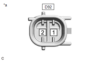
1. INSPECT CAMSHAFT TIMING OIL CONTROL SOLENOID ASSEMBLY (for Intake Side)
(a) Check the resistance.
| (1) Measure the resistance according to the value(s) in the table below. Standard Resistance:
If the result is not as specified, replace the camshaft timing oil control solenoid assembly. |
|
(b) Stroke Amount Inspection
| (1) Using vernier calipers, measure length (A) and (B) with the shaft of the camshaft timing oil control solenoid assembly set in the respective positions shown in the illustration. NOTICE: Do not apply auxiliary battery voltage to the terminals of the camshaft timing oil control solenoid assembly . HINT: If the shaft does not extend under its own weight, extend the shaft with your fingers. |
|
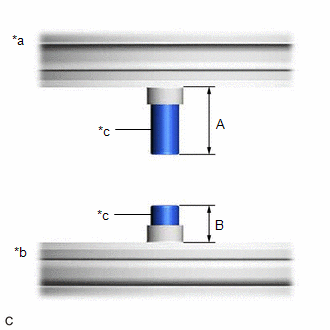
(2) Calculate the stroke amount based on the difference of length (A) and (B).
Standard:
4.3 mm (0.169 in.) or more
HINT:
Stroke amount = length (A) - length (B)
If the value is not as specified, replace the camshaft timing oil control solenoid assembly .
2. INSPECT CAMSHAFT TIMING OIL CONTROL SOLENOID ASSEMBLY (for Exhaust Side)
(a) Check the resistance.
| (1) Measure the resistance according to the value(s) in the table below. Standard Resistance:
If the result is not as specified, replace the camshaft timing oil control solenoid assembly. |
|

(b) Stroke Amount Inspection
| (1) Using vernier calipers, measure length (A) and (B) with the shaft of the camshaft timing oil control solenoid assembly set in the respective positions shown in the illustration. NOTICE: Do not apply auxiliary battery voltage to the terminals of the camshaft timing oil control solenoid assembly . HINT: If the shaft does not extend under its own weight, extend the shaft with your fingers. |
|

(2) Calculate the stroke amount based on the difference of length (A) and (B).
Standard:
4.3 mm (0.169 in.) or more
HINT:
Stroke amount = length (A) - length (B)
If the value is not as specified, replace the camshaft timing oil control solenoid assembly .
 Removal
REMOVAL PROCEDURE 1. REMOVE CAMSHAFT TIMING OIL CONTROL SOLENOID ASSEMBLY (for Intake Side) (a) Disconnect the camshaft timing oil control solenoid assembly connector...
 Installation
INSTALLATION PROCEDURE 1. INSTALL CAMSHAFT TIMING OIL CONTROL SOLENOID ASSEMBLY (for Intake Side) (a) Clean the O-ring groove of the camshaft timing oil control solenoid assembly...
Other information:
Toyota Yaris XP210 (2020-2026) Reapir and Service Manual: Components
C..
Toyota Yaris XP210 (2020-2026) Reapir and Service Manual: Components
COMPONENTS ILLUSTRATION *A for Driver Side *B for Front Passenger Side *1 FRONT DOOR LOWER FRAME BRACKET GARNISH *2 MULTIPLEX NETWORK MASTER SWITCH ASSEMBLY WITH FRONT ARMREST BASE UPPER PANEL *3 POWER WINDOW REGULATOR SWITCH ASSEMBLY WITH FRONT ARMREST BASE UPPER PANEL *4 FRONT DOOR TRIM GARNISH *5 FRONT DOOR TRIM BOARD SUB-ASSEMBLY *6 FRONT DOOR GLASS INNER WEATHERSTRIP ILLUSTRATION *A for Driver Side - - *1 FRONT DOOR SERVICE HOLE COVER *2 FRONT DOOR OUTSIDE HANDLE ASSEMBLY *3 FRONT DOOR LOCK CYLINDER ASSEMBLY *4 FRONT DOOR WITH MOTOR LOCK ASSEMBLY *5 FRONT DOOR LOCK OPEN LEVER REMOTE CONTROL CABLE *6 FRONT DOOR LOCK/UNLOCK KNOB INSIDE LOCKING CABLE *7 DOOR LOCK WIRING HARNESS SEAL *8 FRONT DOOR SERVICE HOLE COVER CLIP *9 HOLE PLUG - - N*m (kgf*cm, ft...
Categories
- Manuals Home
- Toyota Yaris Owners Manual
- Toyota Yaris Service Manual
- Opening and Closing the Liftgate/Trunk Lid
- Fuel Gauge
- Battery Monitor Module General Electrical Failure (P058A01)
- New on site
- Most important about car
Refueling
Before refueling, close all the doors, windows, and the liftgate/trunk lid, and switch the ignition OFF.
To open the fuel-filler lid, pull the remote fuel-filler lid release.
