Toyota Yaris: Front Axle Hub / On-vehicle Inspection
ON-VEHICLE INSPECTION
CAUTION / NOTICE / HINT
HINT:
- The following procedure is for the LH side.
- Use the same procedure for the RH side and LH side.
PROCEDURE
1. REMOVE FRONT WHEEL
Click here

2. SEPARATE FRONT DISC BRAKE CALIPER ASSEMBLY
Click here

3. REMOVE FRONT DISC
Click here

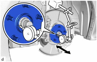
4. INSPECT FRONT AXLE HUB BEARING LOOSENESS
| (a) Using a dial indicator with magnetic base, check for looseness near the center of the front axle hub sub-assembly. Maximum Looseness: 0.05 mm (0.00197 in.) NOTICE:
HINT: If the looseness exceeds the maximum, replace the front axle hub sub-assembly. |
|
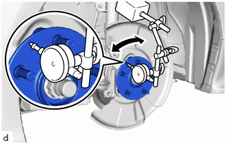
5. INSPECT FRONT AXLE HUB RUNOUT
| (a) Using a dial indicator with magnetic base, check for runout on the surface of the front axle hub sub-assembly outside the front axle hub bolts. Maximum Runout: 0.05 mm (0.00197 in.) NOTICE:
HINT: If the runout exceeds the maximum, replace the front axle hub sub-assembly. |
|
6. INSTALL FRONT DISC
Click here

7. INSTALL FRONT DISC BRAKE CALIPER ASSEMBLY
Click here

8. INSTALL FRONT WHEEL
Click here

 Components
COMPONENTS ILLUSTRATION
*1 FRONT AXLE ASSEMBLY *2 FRONT AXLE SHAFT NUT *3 FRONT DISC *4 FRONT DISC BRAKE CALIPER ASSEMBLY *5 FRONT DRIVE SHAFT ASSEMBLY *6 FRONT LOWER NO...
 Removal
REMOVAL CAUTION / NOTICE / HINT The necessary procedures (adjustment, calibration, initialization, or registration) that must be performed after parts are removed and installed, or replaced during the front axle hub sub-assembly removal/installation are shown below...
Other information:
Toyota Yaris XP210 (2020-2026) Reapir and Service Manual: Door Unlock Detection Switch Circuit
DESCRIPTION The main body ECU (multiplex network body ECU) detects the condition of each door unlock detection switch. WIRING DIAGRAM CAUTION / NOTICE / HINT NOTICE: Before replacing the main body ECU (multiplex network body ECU), refer to Registration...
Toyota Yaris XP210 (2020-2026) Reapir and Service Manual: Left Front Wheel Speed Sensor Signal Has Too Many Pulses (C05003A,C05063A)
DESCRIPTION Refer to DTC C05001F. Click here DTC No. Detection Item DTC Detection Condition Trouble Area DTC Output from C05003A Left Front Wheel Speed Sensor Signal Has Too Many Pulses When not in Dealer Mode (Signal Check) or Inspection Mode, the output of the speed sensor detected by the skid control ECU (brake actuator assembly) is too high for 5 second or more...
Categories
- Manuals Home
- Toyota Yaris Owners Manual
- Toyota Yaris Service Manual
- Power Integration No.1 System Missing Message (B235287,B235587,B235787-B235987)
- Engine Start Function When Key Battery is Dead
- To Set Speed
- New on site
- Most important about car
Fuel-Filler Lid and Cap
WARNING
When removing the fuel-filler cap, loosen the cap slightly and wait for any hissing to stop, then remove it
Fuel spray is dangerous. Fuel can burn skin and eyes and cause illness if ingested. Fuel spray is released when there is pressure in the fuel tank and the fuel-filler cap is removed too quickly.