Toyota Yaris: Cylinder Block / Reassembly
REASSEMBLY
PROCEDURE
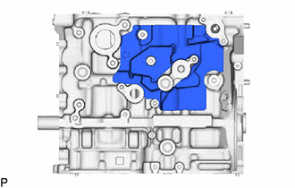
1. INSTALL NO. 3 OIL NOZZLE SUB-ASSEMBLY
(a) Using a 5 mm hexagon wrench, install the 3 No. 3 oil nozzle sub-assemblies to the cylinder block sub-assembly with the 3 bolts.
Torque:
10 N·m {102 kgf·cm, 7 ft·lbf}
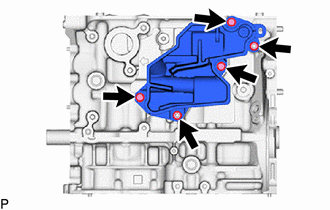
2. INSTALL NO. 2 OIL NOZZLE SUB-ASSEMBLY
(a) Using a 5 mm hexagon wrench, install the 3 No. 2 oil nozzle sub-assemblies to the cylinder block sub-assembly with the 3 bolts.
Torque:
10 N·m {102 kgf·cm, 7 ft·lbf}
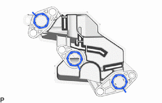
3. INSTALL NO. 1 OIL NOZZLE SUB-ASSEMBLY
(a) Using a 5 mm hexagon wrench, install the 3 No. 1 oil nozzle sub-assemblies to the cylinder block sub-assembly with the 3 bolts.
Torque:
10 N·m {102 kgf·cm, 7 ft·lbf}
4. INSTALL PISTON
HINT:
Perform inspection after repair after replacing the piston.
Click here

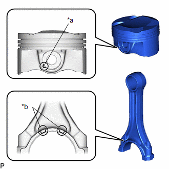
(a) Using a screwdriver, install a new piston pin hole snap ring to the piston pin hole on the rear side of the piston.
NOTICE:
Be sure that the end gap of the piston pin hole snap ring is not aligned with the cutout of the piston.
HINT:
Tape the screwdriver tip before use.
(b) Gradually heat the piston to between 80 and 90°C (176 and 194°F).
CAUTION:
Be sure to wear protective gloves.
(c) Apply a light coat of engine oil to the piston, piston pin and connecting rod.
| (d) Align the cutout of the piston and front mark of the connecting rod, insert the connecting rod into the piston, and then push in the piston pin with your thumb until the piston pin comes into contact with the piston pin hole snap ring. NOTICE: Do not change the combination of the pistons and piston pins. |
|
| (e) Using a screwdriver, install a new piston pin hole snap ring to the piston pin hole on the front side of the piston. NOTICE: Be sure that the end gap of the piston pin hole snap ring is not aligned with the cutout of the piston. HINT: Tape the screwdriver tip before use. |
|
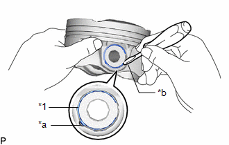
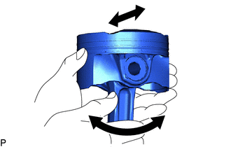
| (f) Check the fitting condition between the piston and piston pin. (1) Move the connecting rod back and forth on the piston pin. Check the fitting condition. HINT: If abnormal movement is felt, replace the piston and piston pin as a set. (2) Rotate the piston back and forth on the piston pin. Check the fitting condition. HINT: If abnormal movement is felt, replace the piston and piston pin as a set. |
|
5. INSTALL PISTON RING SET
HINT:
Perform inspection after repair after replacing the piston and piston ring.
Click here

| (a) Install the oil ring expander by hand. |
|
| (b) Install upper side rail and lower side rail to the piston. NOTICE: Install the upper side rail and lower side rail with the code mark (T) facing upward. |
|
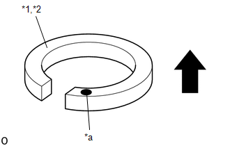
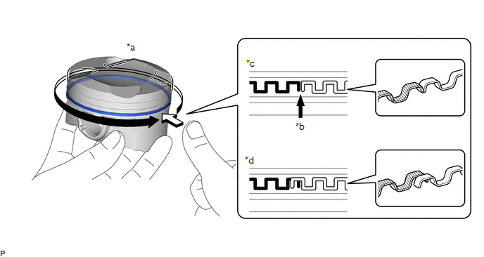
(c) Check that the ends of the oil ring expander are not overlapping and that the upper side rail and lower side rail are securely installed into the groove.

| *a | Press around the circumference | *b | Ring End |
| *c | Correct | *d | Incorrect (Ends of the oil ring expander are overlapping) |
NOTICE:
- After installing the oil ring expander, upper side rail and lower side rail, press around the circumference with a finger to check that they are securely installed into the groove.
- If the oil ring expander is not securely installed into the groove, check that the ends of the oil ring expander are not overlapping.
- If the ends of the oil ring expander are overlapping, remove the upper side rail and lower side rail and realign the oil ring expander.
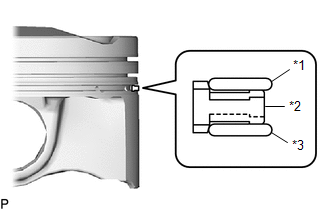
(d) Using a piston ring expander, install the No. 1 compression ring and No. 2 compression ring with the code mark positioned as shown in the illustration.
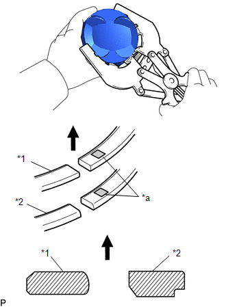
| *1 | No. 1 Compression Ring |
| *2 | No. 2 Compression Ring |
| *a | Code Mark |
 | Upward |
Piston Ring Mark:
| Item | Code Mark | Paint Mark |
|---|---|---|
| No. 1 Compression Ring | T | - |
| No. 2 Compression Ring | 2T | - |
NOTICE:
Install the compression rings with the code marks facing upward.
(e) Position the piston rings so that the ring ends are as shown in the illustration.

| *1 | No. 1 Compression Ring |
| *2 | No. 2 Compression Ring |
| *3 | Oil Ring Expander |
| *4 | Upper Side Rail |
| *5 | Lower Side Rail |
| *a | Front Mark |
 | Front of Engine |
6. INSTALL CRANKSHAFT BEARING
(a) Clean the main journal and both surfaces of the No. 1 crankshaft bearings and No. 2 crankshaft bearings.
| (b) Install the 4 No. 1 crankshaft bearings to the cylinder block sub-assembly as shown in the illustration. NOTICE: Do not apply engine oil to the No. 1 crankshaft bearings or the contact surfaces. HINT: Both sides of the oil groove in the cylinder block sub-assembly should be visible through the oil feed holes in the No. 1 crankshaft bearing. The amount visible on each side of the holes should be equal. |
|
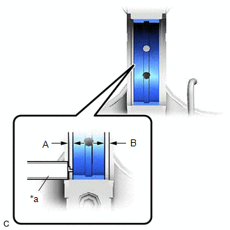
| (c) Using a vernier caliper, measure the distance between the cylinder block sub-assembly edge and the upper No. 1 crankshaft bearing edge. Difference between (A) and (B): 0 to 0.7 mm (0 to 0.0276 in.) |
|
| (d) Install the 4 No. 2 crankshaft bearings to the 5 crankshaft bearing caps. |
|
(e) Using a vernier caliper, measure the distance between the crankshaft bearing cap edge and No. 2 crankshaft bearing edge.
Difference between (A) and (B):
0 to 0.7 mm (0 to 0.0276 in.)
NOTICE:
Do not apply engine oil to the No. 2 crankshaft bearings or the contact surfaces.
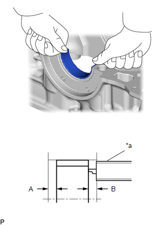
7. INSTALL CRANKSHAFT THRUST WASHER
| (a) Install the 2 crankshaft thrust washers to the No. 3 journal position of the cylinder block sub-assembly with the oil grooves facing outward. |
|
(b) Apply engine oil to the crankshaft thrust washers.
8. INSTALL CRANKSHAFT
(a) Apply engine oil to the No. 1 crankshaft bearings, and place the crankshaft on the cylinder block sub-assembly.
(b) Apply engine oil to the No. 2 crankshaft bearings.
(c) Apply a light coat of engine oil to the threads and under the heads of the crankshaft bearing cap set bolts.
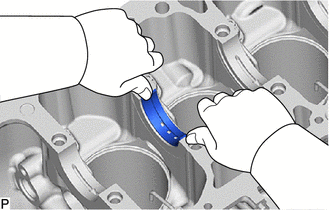
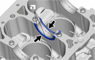
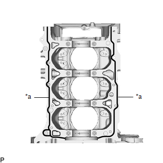
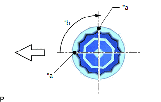
| (d) Apply seal packing in a continuous line as shown in the illustration. Seal Packing: Toyota Genuine Seal Packing Black, Three Bond 1207B or equivalent Standard Seal Packing Dimension: 2.5 to 3.5 mm (0.0984 to 0.138 in.) NOTICE:
|
|
(e) Using a plastic hammer, lightly tap the crankshaft bearing cap assembly to ensure a proper fit.
(f) Install the crankshaft bearing cap set bolts.
NOTICE:
The crankshaft bearing cap set bolts are tightened in 2 progressive steps.
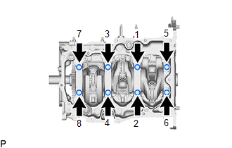
(g) Step 1:
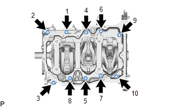
| (1) Uniformly install and tighten the 8 crankshaft bearing cap set bolts in the order shown in the illustration. Torque: 70 N·m {714 kgf·cm, 52 ft·lbf} HINT: If a crankshaft bearing cap set bolt cannot be tightened to the specified torque, replace it. |
|
(h) Step 2:
(1) Mark the front of the crankshaft bearing cap set bolts with paint.
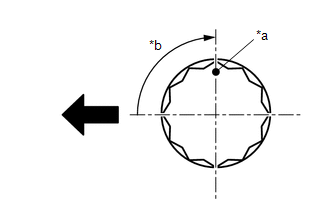
| *a | Paint Mark |
| *b | 90° |
 | Front of Engine |
(2) Tighten the 8 crankshaft bearing cap set bolts 90° as shown in the illustration.
(3) Check that the paint marks are now at a 90° angle to the front.
| (i) Install and tighten the 10 bolts in the order shown in the illustration. Torque: 25 N·m {255 kgf·cm, 18 ft·lbf} |
|
(j) Check that the crankshaft turns smoothly.
9. INSTALL CONNECTING ROD BEARING
| (a) Clean the connecting rod bearing contact surfaces of the connecting rod and connecting rod cap, and both surfaces of the 2 connecting rod bearings. |
|
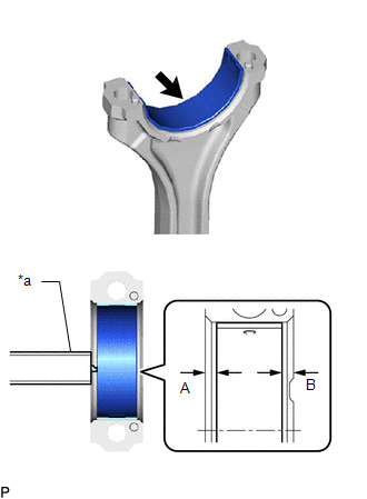
(b) Install the 6 connecting rod bearings to the 3 connecting rods and 3 connecting rod caps.
(c) Using a vernier caliper, measure the distance between the edges of the connecting rod and connecting rod bearing, and the edges of the connecting rod cap and connecting rod bearing.
Difference between (A) and (B):
0 to 0.7 mm (0 to 0.0276 in.)
NOTICE:
Do not apply engine oil to the connecting rod bearings or the contact surfaces.
10. INSTALL PISTON WITH CONNECTING ROD
(a) Apply engine oil to the cylinder walls, pistons, and surfaces of the connecting rod bearings.
(b) Position the piston rings so that the ring ends are as shown in the illustration.
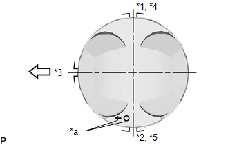
| *1 | No. 1 Compression Ring |
| *2 | No. 2 Compression Ring |
| *3 | Oil Ring Expander |
| *4 | Upper Side Rail |
| *5 | Lower Side Rail |
| *a | Front Mark |
 | Front of Engine |
(c) Confirm that the ends of the oil ring expander are not overlapping and that the upper side rail and lower side rail are securely installed into the groove.
| *a | Press around the circumference | *b | Ring End |
| *c | Correct | *d | Incorrect (Ends of the oil ring expander are overlapping) |
NOTICE:
- After installing the oil ring expander, upper side rail and lower side rail, press around the circumference with a finger to check that they are securely installed into the groove.
- If the oil ring expander is not securely installed into the groove, check that the ends of the oil ring expander are not overlapping.
- If the ends of the oil ring expander are overlapping, remove the upper side rail and lower side rail and realign the oil ring expander.
| (d) Using a piston ring compressor, push the correctly numbered piston with connecting rod into the cylinder with the front marks of each piston with connecting rod facing the front of the engine. NOTICE:
|
|
| (e) Check that the front mark of the connecting rod cap is facing the correct direction. |
|
(f) Apply a light coat of engine oil to the threads and under the heads of the connecting rod bolts.
(g) Install the 6 connecting rod bolts.
NOTICE:
The connecting rod bolts are tightened in 2 progressive steps.
(h) Step 1:
| (1) Using an E12 "TORX" socket wrench, alternately tighten the 2 connecting rod bolts in several steps. Torque: 40 N·m {408 kgf·cm, 30 ft·lbf} |
|
(i) Step 2:
| *a | Paint Mark |
| *b | 90° |
 | Front of Engine |
(1) Mark the front of the connecting rod bolts with paint.
(2) Tighten the connecting rod bolts 90° as shown in the illustration.
(3) Check that the paint marks are now at a 90° angle to the front.
(j) Check that the crankshaft turns smoothly.
(k) Check the connecting rod thrust clearance.
Click here

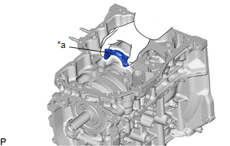
11. INSTALL NO. 1 CYLINDER BLOCK INSULATOR
| (a) Install the No. 1 cylinder block insulator to the cylinder block sub-aseembly. |
|
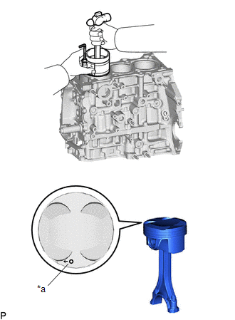
12. INSTALL NO. 1 VENTILATION CASE
NOTICE:
Perform this procedure only when replacement of the No. 1 ventilation case is necessary.
| (a) Install 3 new oil separator gaskets to the No. 1 ventilation case. |
|
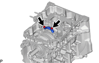
| (b) Install the No. 1 ventilation case to the cylinder block sub-assembly with the 3 bolts and 2 nuts. Torque: 21 N·m {214 kgf·cm, 15 ft·lbf} |
|
 Replacement
REPLACEMENT PROCEDURE 1. REPLACE RING PIN NOTICE: It is not necessary to remove the ring pins unless they are being replaced. (a) Remove the 10 ring pins...

Other information:
Toyota Yaris XP210 (2020-2026) Reapir and Service Manual: Steering Knuckle
ComponentsCOMPONENTS ILLUSTRATION *1 FRONT AXLE HUB SUB-ASSEMBLY *2 FRONT DISC BRAKE DUST COVER *3 STEERING KNUCKLE *4 FRONT LOWER BALL JOINT ASSEMBLY *5 COTTER PIN - - Tightening torque for "Major areas involving basic vehicle performance such as moving/turning/stopping" : N*m (kgf*cm, ft...
Toyota Yaris XP210 (2020-2026) Reapir and Service Manual: Diagnostic Trouble Code Chart
D..
Categories
- Manuals Home
- Toyota Yaris Owners Manual
- Toyota Yaris Service Manual
- Engine & Hybrid System
- Fuse Panel Description
- Power Integration No.1 System Missing Message (B235287,B235587,B235787-B235987)
- New on site
- Most important about car
Keys

To use the auxiliary key, press the knob and pull out the auxiliary key from the smart key.
