Toyota Yaris: Cylinder Block / Replacement
REPLACEMENT
PROCEDURE
1. REPLACE RING PIN
NOTICE:
It is not necessary to remove the ring pins unless they are being replaced.
(a) Remove the 10 ring pins.
(b) Using a plastic hammer, install 10 new ring pins.
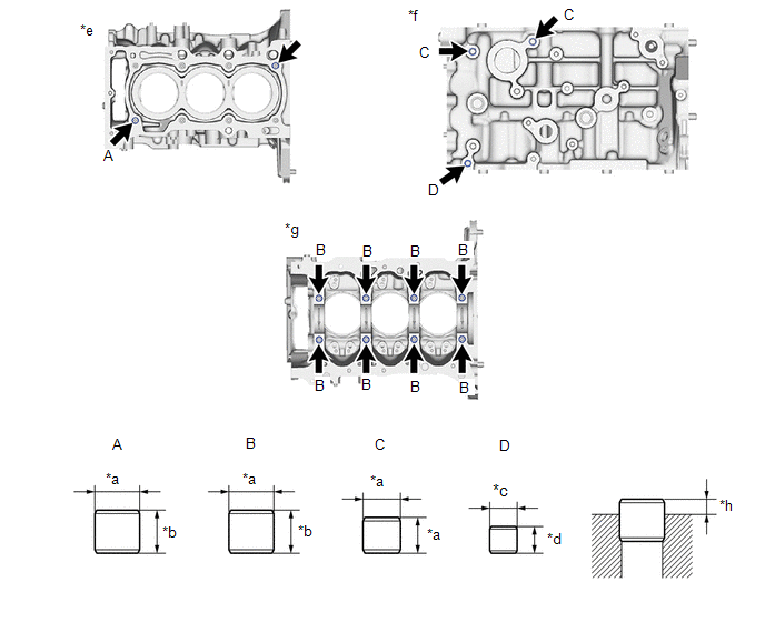
| *a | 14 mm (0.551 in.) | *b | 12 mm (0.472 in.) |
| *c | 11 mm (0.433 in.) | *d | 8 mm (0.315 in.) |
| *e | Top Side | *f | LH Side |
| *g | Bottom Side | *h | Protrusion Height |
Standard Protrusion Height:
RING PIN (A, B, C)
5.0 to 7.0 mm (0.197 to 0.276 in.)
RING PIN (D)
3.0 to 5.0 mm (0.118 to 0.197 in.)
2. REPLACE STRAIGHT PIN
NOTICE:
It is not necessary to remove the straight pins unless they are being replaced.
(a) Remove the 8 straight pins.
(b) Using a plastic hammer, install 8 new straight pins.
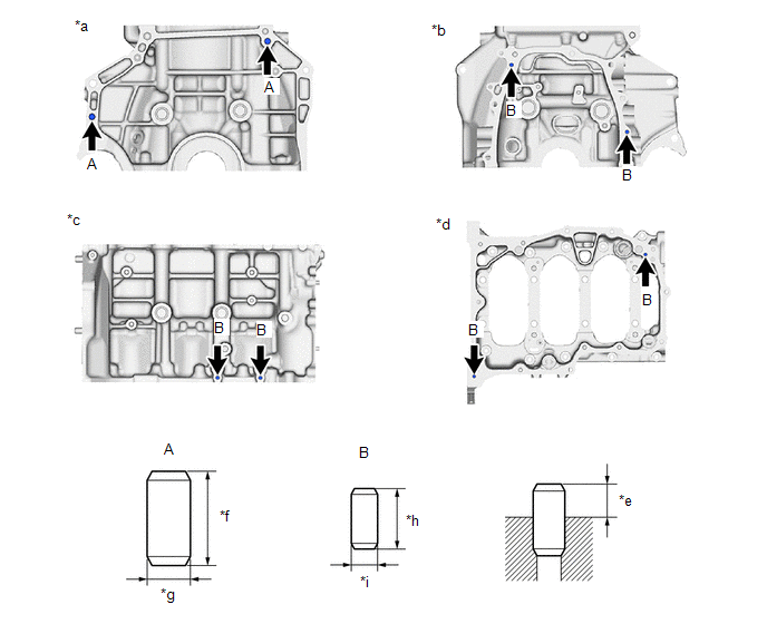
| *a | Rear Side | *b | Front Side |
| *c | RH Side | *d | Bottom Side |
| *e | Protrusion Height | *f | 22 mm (0.866 in.) |
| *g | 10 mm (0.394 in.) | *h | 14 mm (0.551 in.) |
| *i | 6.0 mm (0.236 in.) | - | - |
Standard Protrusion Height:
| Straight Pin | Specified Condition |
|---|---|
| (A) | 11.0 to 13.0 mm (0.433 to 0.512 in.) |
| (B) | 5.0 to 7.0 mm (0.197 to 0.276 in.) |
 Inspection
INSPECTION PROCEDURE 1. INSPECT CYLINDER BLOCK FOR WARPAGE (a) Using a precision straightedge and feeler gauge, check the surface which contacts the cylinder head gasket for warpage...
 Reassembly
REASSEMBLY PROCEDURE 1. INSTALL NO. 3 OIL NOZZLE SUB-ASSEMBLY (a) Using a 5 mm hexagon wrench, install the 3 No. 3 oil nozzle sub-assemblies to the cylinder block sub-assembly with the 3 bolts...
Other information:
Toyota Yaris XP210 (2020-2026) Reapir and Service Manual: Removal
REMOVAL PROCEDURE 1. REMOVE NO. 1 INSTRUMENT PANEL UNDER COVER SUB-ASSEMBLY Click here 2. REMOVE BRAKE PEDAL RETURN SPRING Click here 3. REMOVE CLUTCH PEDAL STROKE SENSOR ASSEMBLY (a) Disconnect the clutch pedal stroke sensor assembly connector...
Toyota Yaris XP210 (2020-2026) Reapir and Service Manual: Inspection
INSPECTION PROCEDURE 1. INSPECT KNOCK SENSOR (a) Measure the resistance according to the value(s) in the table below. Standard Resistance: Tester Connection Condition Specified Condition e1-1 - e1-2 25°C (77°F) 120 to 280 kΩ If the result is not as specified, replace the knock sensor...
Categories
- Manuals Home
- Toyota Yaris Owners Manual
- Toyota Yaris Service Manual
- Adjustment
- Headlights
- Battery Monitor Module General Electrical Failure (P058A01)
- New on site
- Most important about car
Front Seat Belt Pretensioners
The front seat belt pretensioners are designed to deploy in moderate or severe frontal, near frontal collisions.
In addition, the pretensioners operate when a side collision or a rollover accident is detected. The pretensioners operate differently depending on what types of air bags are equipped. For more details about the seat belt pretensioner operation, refer to the SRS Air Bag Deployment Criteria.