Toyota Yaris: Cylinder Block / Inspection
INSPECTION
PROCEDURE
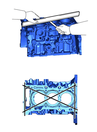
1. INSPECT CYLINDER BLOCK FOR WARPAGE
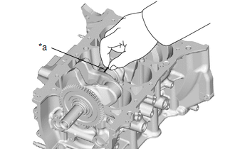
| (a) Using a precision straightedge and feeler gauge, check the surface which contacts the cylinder head gasket for warpage. Maximum Warpage: 0.05 mm (0.00197 in.) HINT: If the warpage is more than the maximum, replace the cylinder block sub-assembly. |
|
2. INSPECT CYLINDER BORE
(a) Using a cylinder gauge, measure the cylinder bore diameter at the positions (A) and (B) in the thrust and axial directions.
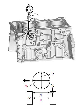
| *a | Thrust Direction |
| *b | Axial Direction |
| *c | 10 mm (0.394 in.) |
| *d | Center |
 | Front of Engine |
Reference Diameter (New Parts):
87.500 to 87.513 mm (3.4449 to 3.4454 in.)
Maximum Diameter:
87.514 mm (3.4454 in.)
HINT:
If the average diameter of 4 positions is more than the maximum, replace the cylinder block sub-assembly.
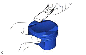
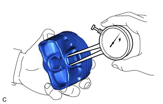
3. INSPECT PISTON
| (a) Using a gasket scraper, remove any carbon from the piston top. |
|
| (b) Using a groove cleaning tool or a broken ring, clean the piston ring grooves. |
|
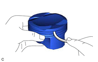
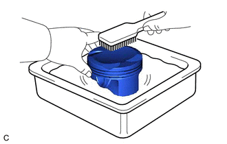
| (c) Using a brush and solvent, thoroughly clean the piston. NOTICE: Do not use a wire brush. |
|
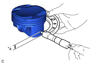
| (d) Using a micrometer, measure the piston diameter at a right angle to the piston center line where the distance from the bottom of the piston is as specified. Distance: 10.5 mm (0.413 in.) Standard Piston Diameter (New Parts): 87.459 to 87.471 mm (3.443 to 3.444 in.) HINT: If the diameter is less than the minimum, replace the piston and piston pin as a set. |
|
4. INSPECT PISTON OIL CLEARANCE
(a) Subtract the piston diameter measurement from the cylinder bore diameter measurement.
Reference Oil Clearance (New Parts):
0.029 to 0.054 mm (0.00114 to 0.00213 in.)
Maximum Oil Clearance:
0.065 mm (0.00256 in.)
HINT:
If the piston oil clearance is more than the maximum, replace all the pistons with piston pins. If necessary, replace the cylinder block sub-assembly.
5. INSPECT RING GROOVE CLEARANCE
| (a) Using a feeler gauge, measure the clearance between a new piston ring set and the wall of the ring groove. Standard Ring Groove Clearance:
HINT: If the groove clearance is not as specified, replace the piston and piston pin as a set. |
|
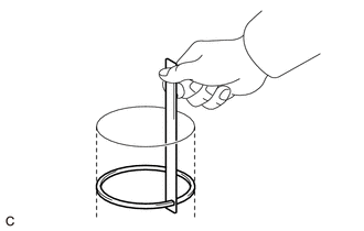
6. INSPECT PISTON RING END GAP
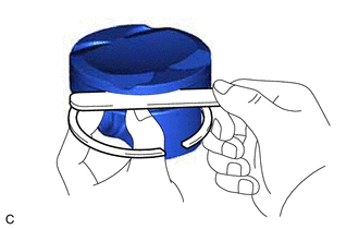
| (a) Insert the piston ring into the cylinder bore. |
|
(b) Using a piston, push in the piston ring a little beyond the bottom of the ring travel, 70 mm (2.76 in.) from the top of the cylinder block sub-assembly.
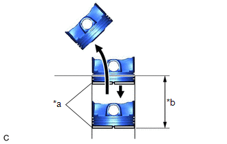
| (c) Using a feeler gauge, measure the end gap. Standard End Gap:
Maximum End Gap:
HINT: If the end gap is more than the maximum, replace the piston ring set. If the end gap is more than the maximum even with a new piston ring set, replace the cylinder block sub-assembly. |
|
7. INSPECT PISTON PIN OIL CLEARANCE
HINT:
When replacing the piston and piston pin with supply parts, there are a number of piston diameter sizes to choose from, but there is only one size of piston pin diameter.
(a) Confirm each mark on the piston, piston pin and connecting rod.
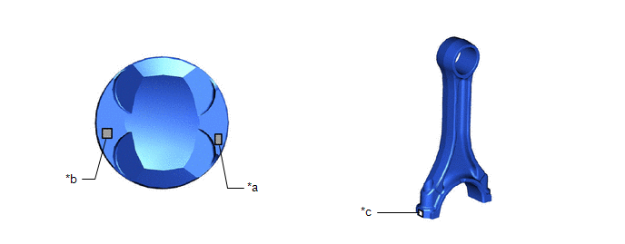
| *a | Front Mark | *b | Piston Pin Hole Inside Diameter Mark |
| *c | Connecting Rod Small End Bush Inside Diameter Mark | - | - |
| (b) Using a caliper gauge, measure the inside diameter of the piston pin hole. Standard Piston Pin Hole Inside Diameter: 19.009 to 19.018 mm (0.748 to 0.749 in.)
HINT: If the diameter is not as specified, replace the piston and piston pin as a set. |
|
| (c) Using a micrometer, measure the piston pin diameter. Standard Piston Pin Diameter: 19.004 to 19.013 mm (0.74819 to 0.74854 in.)
HINT: If the diameter is not as specified, replace the piston and piston pin as a set. Measurement Position:
|
|
| (d) Using a caliper gauge, measure the inside diameter of the connecting rod small end bush. Standard Connecting Rod Small End Bush Inside Diameter: 19.012 to 19.021 mm (0.74850 to 0.74886 in.)
HINT: If the inside diameter is not as specified, replace the connecting rod sub-assembly. |
|
(e) Subtract the piston pin diameter measurement from the piston pin hole inside diameter measurement.
Standard Oil Clearance:
0.001 to 0.004 mm (0.0000394 to 0.0001575 in.)
Maximum Oil Clearance:
0.017 mm (0.000669 in.)
HINT:
If the oil clearance is more than the maximum, replace the piston and piston pin as a set.
(f) Subtract the piston pin diameter measurement from the connecting rod small end bush inside diameter measurement.
Standard Oil Clearance:
0.005 to 0.011 mm (0.000197 to 0.000433 in.)
Maximum Oil Clearance:
0.021 mm (0.000827 in.)
HINT:
If the oil clearance is more than the maximum, replace the connecting rod sub-assembly. If necessary, replace the connecting rod sub-assembly and piston pin as a set.
8. INSPECT CRANKSHAFT
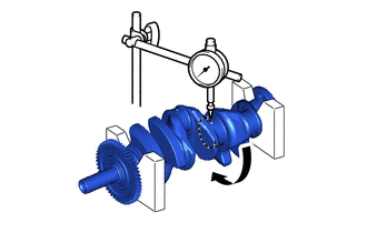
(a) Inspect for runout.
(1) Clean the crank journal.
(2) Place the crankshaft on V-blocks.
| (3) Using a dial indicator and V-blocks, measure the runout as shown in the illustration. Maximum Runout: 0.03 mm (0.00118 in.) HINT: If the runout is more than the maximum, replace the crankshaft. |
|
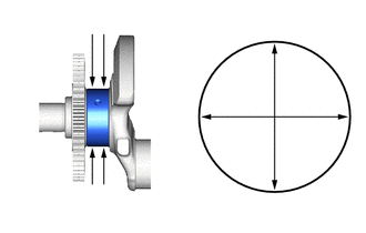
(b) Inspect the main journals.
(1) Using a micrometer, measure the diameter of each main journal.
Standard Main Journal Diameter:
55.988 to 56.000 mm (2.204 to 2.205 in.)
HINT:
If the diameter is not as specified, check the crankshaft oil clearance. If necessary, replace the crankshaft.
| (2) Check each main journal for taper and out-of-round as shown in the illustration. Maximum Taper and Out-of-round: 0.003 mm (0.000118 in.) HINT: If the taper or out-of-round is more than the maximum, replace the crankshaft. |
|
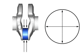
(c) Inspect the crank pins.
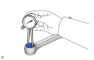
(1) Using a micrometer, measure the diameter of each crank pin.
Standard Crank Pin Diameter:
47.992 to 48.000 mm (1.88945 to 1.88976 in.)
HINT:
If the diameter is not as specified, check the connecting rod oil clearance. If necessary, replace the crankshaft.
| (2) Inspect each crank pin for taper and out-of-round as shown in the illustration. Maximum Taper and Out-of-round: 0.003 mm (0.000118 in.) HINT: If the taper or out-of-round is more than the maximum, replace the crankshaft. |
|
9. INSPECT CRANKSHAFT OIL CLEARANCE
(a) Install the crankshaft bearings.
Click here

(b) Install the crankshaft thrust washers.
Click here

(c) Place the crankshaft on the cylinder block sub-assembly.
| (d) Lay a strip of Plastigage across each journal. |
|
(e) Install the crankshaft bearing caps.
Click here

NOTICE:
Do not turn the crankshaft.
(f) Remove the crankshaft bearing caps.
Click here

(g) Measure the Plastigage at its widest point.
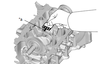
| *a | Plastigage |
Standard Oil Clearance:
0.026 to 0.049 mm (0.00102 to 0.00193 in.)
Maximum Oil Clearance:
0.049 mm (0.00193 in.)
NOTICE:
Remove the Plastigage completely after the measurement.
If the oil clearance is more than the maximum, replace the crankshaft bearing. If necessary, replace the crankshaft.
HINT:
If replacing a crankshaft bearing, select a new one with the same number. If the number of the crankshaft bearing cannot be determined, calculate the correct crankshaft bearing number by adding together the numbers imprinted on the cylinder block sub-assembly and crankshaft. Then refer to the following table for the appropriate crankshaft bearing number. There are 4 sizes of standard bearings, marked "1", "2", "3" or "4" accordingly.
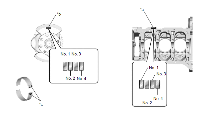
| *a | Cylinder Block Number Mark (A) | *b | Crankshaft Number Mark (B) |
| *c | Diameter Mark | - | - |
-
EXAMPLE
Cylinder block sub-assembly (A) "3" + Crankshaft (B) "4" = Total "7"
Select the crankshaft bearing marked "3".
Crankshaft Bearing Chart:
(A) + (B)
Use Crankshaft Bearing
0 to 2
1
3 to 5
2
6 to 8
3
9 to 11
4
Standard Cylinder Block Journal Inside Diameter (A):
Mark
Specified Condition
0
60.000 to 60.003 mm (2.3622 to 2.3623 in.)
1
60.003 to 60.005 mm (2.3623 to 2.3624 in.)
2
60.005 to 60.007 mm (2.3624 to 2.3625 in.)
3
60.007 to 60.010 mm (2.3625 to 2.3626 in.)
4
60.010 to 60.012 mm (2.3626 to 2.3627 in.)
5
60.012 to 60.014 mm (2.3627 to 2.3628 in.)
6
60.014 to 60.016 mm (2.3628 to 2.3628 in.)
Standard Crankshaft Main Journal Diameter (B):
Mark
Specified Condition
0
55.998 to 56.000 mm (2.20464 to 2.20472 in.)
1
55.996 to 55.998 mm (2.20456 to 2.20464 in.)
2
55.994 to 55.996 mm (2.20448 to 2.20456 in.)
3
55.992 to 55.994 mm (2.20441 to 2.20448 in.)
4
55.990 to 55.992 mm (2.20433 to 2.20441 in.)
5
55.988 to 55.990 mm (2.20425 to 2.20433 in.)
Standard Crankshaft Bearing Center Wall Thickness:
Mark
Specified Condition
1
1.993 to 1.996 mm (0.07846 to 0.07858 in.)
2
1.996 to 1.999 mm (0.07858 to 0.07870 in.)
3
1.999 to 2.002 mm (0.07870 to 0.07882 in.)
4
2.002 to 2.005 mm (0.07882 to 0.07894 in.)
(h) Perform the inspection for each journal.
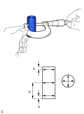
10. INSPECT CRANKSHAFT BEARING CAP SET BOLT
(a) Using a vernier caliper, measure the outer diameter at position (A) shown in the illustration.
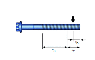
| *a | Measurement Area (B) |
| *b | 5.0 mm (0.197 in.) |
| *c | 10 mm (0.394 in.) |
 | Measurement Location (A) |
Standard Diameter:
10.73 to 10.97 mm (0.422 to 0.432 in.)
(b) Using a vernier caliper, measure the outer diameter within range (B) shown in the illustration at several locations.
HINT:
- Perform the measurement within range (B) at several locations.
- If the threads of the crankshaft bearing cap set bolt are damaged, replace the bolt with a new one.
(c) Calculate the difference between the measurement at position (A) and position (B).
Minimum Diameter:
The outer diameter difference is 0.3 mm (0.0118 in.)
HINT:
- Outer Diameter Difference = Position (A) Outer Diameter - Position (B) Outer Diameter (Smallest Value)
-
If the outer diameter is below the minimum, the engine may be damaged.
Therefore, replace the crankshaft bearing cap set bolt with a new one.
11. INSPECT CONNECTING ROD BOLT
(a) Using a vernier caliper, measure the outer diameter at position (A) shown in the illustration.
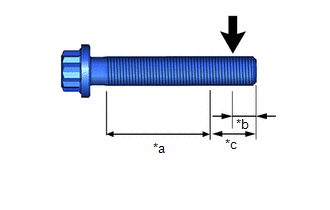
| *a | Measurement Area (B) |
| *b | 5.0 mm (0.197 in.) |
| *c | 10 mm (0.394 in.) |
 | Measurement Location (A) |
Standard Diameter:
8.36 to 8.5 mm (0.329 to 0.335 in.)
(b) Using a vernier caliper, measure the outer diameter within range (B) shown in the illustration at several locations.
HINT:
- Perform the measurement within range (B) at several locations.
- If the threads of the connecting rod bolt are damaged, replace the bolt with a new one.
(c) Calculate the difference between the measurement at position (A) and position (B).
Minimum Diameter:
The outer diameter difference is 0.05 mm (0.00197 in.)
HINT:
- Outer Diameter Difference = Position (A) Outer Diameter - Position (B) Outer Diameter (Smallest Value)
-
If the outer diameter is below the minimum, the engine may be damaged.
Therefore, replace the connecting rod bolt with a new one.
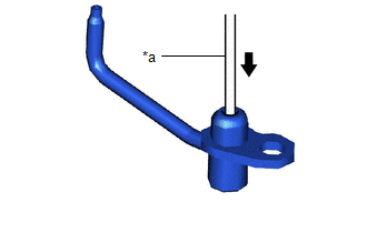
12. INSPECT OIL NOZZLE SUB-ASSEMBLY
| (a) Push the check valve with a pin to check that it is not stuck. HINT: If the check valve is stuck, replace the oil nozzle sub-assembly. |
|
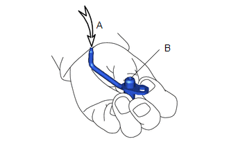
| (b) Apply air into (A). Check that air does not leak through (B). HINT: If air leaks, clean or replace the oil nozzle sub-assembly. |
|
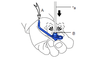
| (c) Push the check valve with a pin while applying air into (A). Check that air passes through (B). HINT: If air does not pass through (B), clean or replace the oil nozzle sub-assembly. |
|
 Disassembly
DISASSEMBLY CAUTION / NOTICE / HINT The necessary procedures (adjustment, calibration, initialization, or registration) that must be performed after parts are removed and installed, or replaced during cylinder block removal/installation are shown below...
 Replacement
REPLACEMENT PROCEDURE 1. REPLACE RING PIN NOTICE: It is not necessary to remove the ring pins unless they are being replaced. (a) Remove the 10 ring pins...
Other information:
Toyota Yaris XP210 (2020-2026) Reapir and Service Manual: Utility
UTILITY Front Beam Axis Adjustment HINT: Front Beam Axis Adjustment is used to calibrate the beam axis of millimeter wave radar sensor assembly. (a) Perform Front Beam Axis Adjustment according to the display on the GTS. Body Electrical > Front Radar Sensor > Utility Tester Display Front Beam Axis Adjustment Front Beam Axis Misalignment Reading HINT: Front Beam Axis Misalignment Reading is used to check the amount of misalignment of the millimeter wave radar sensor assembly...
Toyota Yaris XP210 (2020-2026) Owner's Manual: Picture Quality Adjustment
Picture quality adjustment can be done while the shift lever is in reverse (R). There are four settings which can be adjusted including, brightness, contrast, tint, and color. When adjusting, pay sufficient attention to the vehicle surroundings...
Categories
- Manuals Home
- Toyota Yaris Owners Manual
- Toyota Yaris Service Manual
- Brake System Control Module "A" System Voltage System Voltage Low (C137BA2)
- Adjustment
- Immobilizer System
- New on site
- Most important about car
Turning the Engine Off
Stop the vehicle completely. Manual transaxle: Shift into neutral and set the parking brake.Automatic transaxle: Shift the selector lever to the P position and set the parking brake.
Press the push button start to turn off the engine. The ignition position is off.