Toyota Yaris: Cylinder Block / Disassembly
DISASSEMBLY
CAUTION / NOTICE / HINT
The necessary procedures (adjustment, calibration, initialization, or registration) that must be performed after parts are removed and installed, or replaced during cylinder block removal/installation are shown below.
Necessary Procedure After Parts Removed/Installed/Replaced| Replaced Part or Performed Procedure | Necessary Procedure | Effect/Inoperative Function when Necessary Procedure not Performed | Link |
|---|---|---|---|
| Piston or piston ring | Inspection after repair |
|
|

PROCEDURE
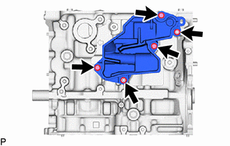
1. REMOVE NO. 1 VENTILATION CASE
CAUTION:
Do not diassembly except if the No. 1 ventilaion case to be damaged.
| (a) Remove the 3 bolts, 2 nuts and No. 1 ventilation case from the cylinder block sub-assembly. |
|
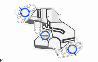
| (b) Remove the 3 oil separator gaskets from the No. 1 ventilation case. |
|
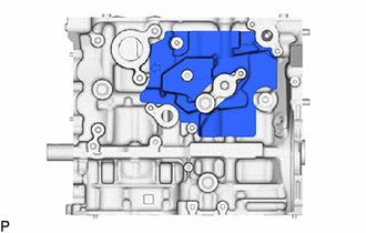
2. REMOVE NO. 1 CYLINDER BLOCK INSULATOR
| (a) Remove the No. 1 cylinder block insulator from the cylinder block sub-aseembly. |
|
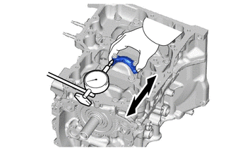
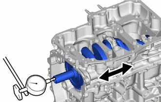
3. INSPECT CONNECTING ROD THRUST CLEARANCE
| (a) Using a dial indicator, measure the thrust clearance while moving the connecting rod sub-assembly back and forth. Standard Thrust Clearance: 0.15 to 0.50 mm (0.00591 to 0.01969 in.) Maximum Thrust Clearance: 0.50 mm (0.01969 in.) HINT: If the thrust clearance is more than the maximum, replace the connecting rod. If necessary, replace the crankshaft. |
|
4. INSPECT CONNECTING ROD OIL CLEARANCE
| (a) Note the alignment marks on the connecting rod and connecting rod cap so that they can be reinstalled to their original locations. |
|
| (b) Using an SST wrench, remove the 2 connecting rod bolts and connecting rod cap. SST: 09205-16011 HINT: Keep the connecting rod bearing and connecting rod cap together. |
|
(c) Clean the crank pin and connecting rod bearing.
(d) Check the crank pin and connecting rod bearing for pitting and scratches.
HINT:
If the crank pin or connecting rod bearing is damaged, replace the connecting rod bearings. If necessary, replace the crankshaft.
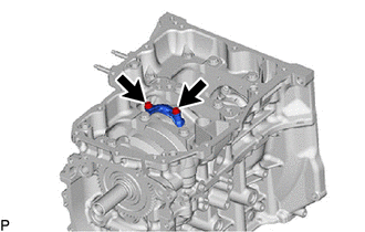
| (e) Lay a strip of Plastigage on the crank pin. |
|
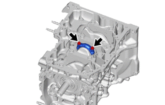
| (f) Check that the front mark of the connecting rod cap is facing the correct direction, and install the connecting rod cap to the connecting rod. |
|
| (g) Apply a light coat of engine oil to the threads and under the heads of the 2 connecting rod bolts. |
|
(h) Using an SST, install and alternately tighten the 2 connecting rod bolts in several steps.
SST: 09205-16011
Torque:
50 N·m {510 kgf·cm, 37 ft·lbf}
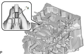
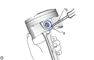
(i) Mark the front of each connecting rod bolt with paint.
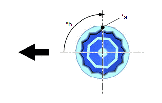
| *a | Paint Mark |
| *b | 90° |
 | Front of Engine |
(j) Tighten the connecting rod bolts 90° as shown in the illustration.
NOTICE:
Do not turn the crankshaft during the measurement.
(k) Remove the 2 connecting rod bolts and connecting rod cap.
HINT:
Keep the connecting rod bearing and connecting rod cap together.
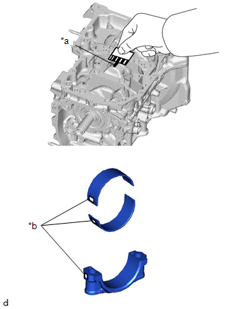
| (l) Measure the Plastigage at its widest point. Standard Oil Clearance: 0.032 to 0.065 mm (0.00126 to 0.00256 in.) Maximum Oil Clearance: 0.065 mm (0.00256 in.) HINT:
Standard Connecting Rod Big End Inside Diameter:
Standard Connecting Rod Bearing Center Wall Thickness:
Standard Crank Pin Diameter: 47.992 to 48.000 mm (1.88945 to 1.88976 in.) NOTICE: Remove the Plastigage completely after the measurement. |
|
(m) Perform the inspection above for each cylinder.
5. REMOVE PISTON WITH CONNECTING ROD
(a) Using a ridge reamer, remove all the carbon from the top of each cylinder.
(b) Remove the 6 connecting rod bolts, 3 connecting rod caps and 3 connecting rod bearings.
(c) Push the 4 pistons, 4 connecting rods and 4 connecting rod bearings out through the top of the cylinder block sub-assembly.
HINT:
- Keep the connecting rod bearings, connecting rods and connecting rod caps together.
- Arrange the removed parts in such a way that they can be reinstalled to their original locations.
6. REMOVE CONNECTING ROD BEARING
(a) Remove the 6 connecting rod bearings from the 3 connecting rods and 3 connecting rod caps.
HINT:
Arrange the removed parts in such a way that they can be reinstalled to their original locations.
7. INSPECT CRANKSHAFT THRUST CLEARANCE
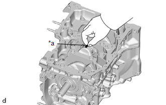
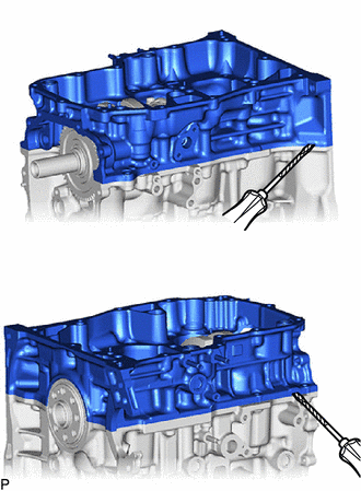
| (a) Using a dial indicator, measure the crankshaft thrust clearance while prying the crankshaft back and forth with a screwdriver. Standard Thrust Clearance: 0.02 to 0.22 mm (0.000787 to 0.00866 in.) Maximum Thrust Clearance: 0.22 mm (0.00866 in.) HINT: If the thrust clearance is more than the maximum, replace the crankshaft thrust washers as a set. If necessary, replace the crankshaft. Standard Thrust Washer Thickness: 2.415 to 2.470 mm (0.0951 to 0.0972 in.) |
|
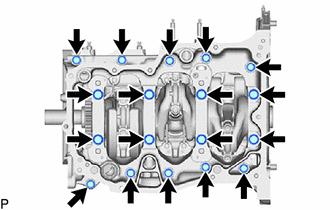
8. REMOVE CRANKSHAFT
| (a) Uniformly loosen and remove the 8 crankshaft bearing cap set bolts and 10 bolts. |
|
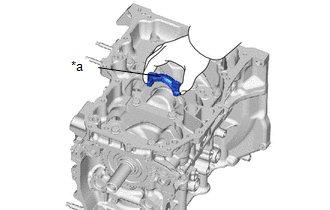
| (b) Remove the crankshaft bearing cap assembly from the cylinder block sub-assembly with a screwdriver with its tip wrapped with protective tape.. HINT:
|
|
(c) Remove the crankshaft from the cylinder block sub-assembly.
HINT:
Keep the crankshaft bearings and crankshaft thrust washers together with the cylinder block sub-assembly.
(d) Check each crankshaft journal and crankshaft bearing for pitting and scratches.
If the journal or crankshaft bearing is damaged, replace the crankshaft bearings. If necessary, replace the crankshaft.
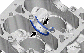
9. REMOVE CRANKSHAFT THRUST WASHER
| (a) Remove the 2 crankshaft thrust washers from the No. 3 journal position of the cylinder block sub-assembly. |
|
10. REMOVE CRANKSHAFT BEARING
(a) Remove the 4 No. 1 crankshaft bearings and 4 No. 2 crankshaft bearings from the cylinder block sub-assembly and crankshaft bearing cap assembly.
HINT:
Arrange the removed parts in such a way that they can be reinstalled to their original locations.
11. REMOVE PISTON RING SET
| (a) Using a piston ring expander, remove the No. 1 compression ring and No. 2 compression ring from the piston. |
|
(b) Remove the oil ring expander, upper side rail and lower side rail from the piston by hand.
HINT:
Arrange the removed parts in such a way that they can be reinstalled to their original locations.
12. REMOVE PISTON PIN HOLE SNAP RING
| (a) Using a screwdriver, pry out the 2 piston pin hole snap rings from the piston. HINT: Tape the screwdriver tip before use. |
|
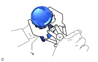
13. REMOVE PISTON
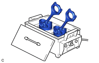
| (a) Gradually heat each piston to between 80 and 90°C (176 to 194°F). CAUTION: Be sure to wear protective gloves. |
|
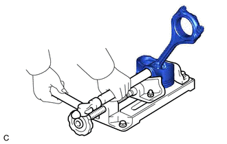
| (b) Using a brass bar and a hammer, lightly tap out the piston pin and remove the connecting rod. HINT:
|
|
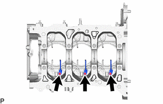
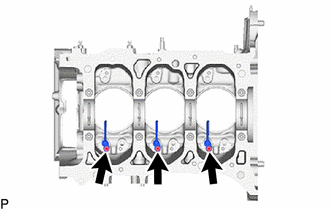
14. REMOVE NO. 1 OIL NOZZLE SUB-ASSEMBLY
| (a) Using a 5 mm hexagon wrench, remove the 3 bolts and 3 No. 1 oil nozzle sub-assemblies from the cylinder block sub-assembly. |
|
15. REMOVE NO. 2 OIL NOZZLE SUB-ASSEMBLY
| (a) Using a 5 mm hexagon wrench, remove the 3 bolts and 3 No. 2 oil nozzle sub-assemblies from the cylinder block sub-assembly. |
|
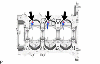
16. REMOVE NO. 3 OIL NOZZLE SUB-ASSEMBLY
| (a) Using a 5 mm hexagon wrench, remove the 3 bolts and 3 No. 3 oil nozzle sub-assemblies from the cylinder block sub-assembly. |
|
 Components
COMPONENTS ILLUSTRATION
*1 RING PIN *2 STRAIGHT PIN *3 STUD BOLT *4 NO. 3 OIL NOZZLE SUB-ASSEMBLY *5 NO. 2 OIL NOZZLE SUB-ASSEMBLY *6 NO...
 Inspection
INSPECTION PROCEDURE 1. INSPECT CYLINDER BLOCK FOR WARPAGE (a) Using a precision straightedge and feeler gauge, check the surface which contacts the cylinder head gasket for warpage...
Other information:
Toyota Yaris XP210 (2020-2026) Reapir and Service Manual: Removal
REMOVAL CAUTION / NOTICE / HINT The necessary procedures (adjustment, calibration, initialization, or registration) that must be performed after parts are removed, installed, or replaced during the curtain shield airbag assembly removal/installation are shown below...
Toyota Yaris XP210 (2020-2026) Reapir and Service Manual: Engine
ENGINE HINT: Perform these procedures after the engine has cooled down. INSPECT DRIVE BELT (a) Inspect the drive belt. Click here INSPECT ENGINE OIL (a) Inspect the engine oil. Click here REPLACE ENGINE OIL AND OIL FILTER (a) Replace the engine oil and oil filter...
Categories
- Manuals Home
- Toyota Yaris Owners Manual
- Toyota Yaris Service Manual
- Key Battery Replacement
- G16e-gts (engine Mechanical)
- To Set Speed
- New on site
- Most important about car
Supplemental Restraint System (SRS) Precautions
The front and side supplemental restraint systems (SRS) include different types of air bags. Please verify the different types of air bags which are equipped on your vehicle by locating the “SRS AIRBAG” location indicators. These indicators are visible in the area where the air bags are installed.
The air bags are installed in the following locations:
The steering wheel hub (driver air bag) The front passenger dashboard (front passenger air bag) The outboard sides of the front seatbacks (side air bags) The front and rear window pillars, and the roof edge along both sides (curtain air bags)