Toyota Yaris: Vehicle Stability Control System / Stop Lamp Relay Actuator Stuck Off (C13807F)
DESCRIPTION
Refer to DTC C13807E.
Click here

| DTC No. | Detection Item | DTC Detection Condition | Trouble Area | DTC Output from |
|---|---|---|---|---|
| C13807F | Stop Lamp Relay Actuator Stuck Off | Either of the following is detected:
|
| Brake |
WIRING DIAGRAM
Refer to DTC C13807E.
Click here

CAUTION / NOTICE / HINT
NOTICE:
After replacing the skid control ECU (brake actuator assembly), perform "Calibration".
Click here

PROCEDURE
| 1. | CHECK STOP LIGHT OPERATION (FOR LED HEADLIGHT) |
(a) Check that the stop lights come on when the brake pedal is depressed.
OK:
The stop lights illuminate.
| NG |
 | GO TO STEP 6 |
|

| 2. | PERFORM ACTIVE TEST USING GTS (STOP LAMP RELAY) |
(a) Perform the Active Test of the stop light relay using the GTS.
Chassis > Brake > Active Test| Tester Display | Measurement Item | Restrict Condition | Diagnostic Note |
|---|---|---|---|
| Stop Lamp Relay | STPO terminal output OFF / ON | Vehicle condition: Vehicle stopped HINT: To protect this Actuator and Solenoid, this test will only last 5 seconds. | - |
| Tester Display |
|---|
| Stop Lamp Relay |
(b) According to the display on the GTS, perform the Active Test and check the operation of the stop lights.
OK:
Stop lights turn on in accordance with the Active Test.
| NG |
 | GO TO STEP 4 |
|

| 3. | CHECK HARNESS AND CONNECTOR (STOP LIGHT SIGNAL INPUT CIRCUIT) |
(a) Turn the ignition switch off.
(b) Make sure that there is no looseness at the locking part and the connecting part of the connectors.
OK:
The connector is securely connected.
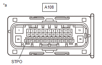
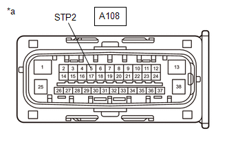
| (c) Disconnect the A108 skid control ECU (brake actuator assembly) connector. |
|

(d) Check both the connector case and the terminals for deformation and corrosion.
OK:
No deformation or corrosion.
(e) Measure the voltage according to the value(s) in the table below.
Standard Voltage:
| Tester Connection | Condition | Specified Condition |
|---|---|---|
| A108-5 (STP2) - Body ground | Brake pedal depressed | 11 to 14 V |
| OK |
 | REPLACE BRAKE ACTUATOR ASSEMBLY |
| NG |
 | REPAIR OR REPLACE HARNESS OR CONNECTOR |
| 4. | CHECK HARNESS AND CONNECTOR (STOP LIGHT ILLUMINATION OUTPUT CIRCUIT) |
(a) Turn the ignition switch off.
(b) Make sure that there is no looseness at the locking part and the connecting part of the connectors.
OK:
The connector is securely connected.
| (c) Disconnect the A108 skid control ECU (brake actuator assembly) connector. |
|
(d) Check both the connector case and the terminals for deformation and corrosion.
OK:
No deformation or corrosion.
(e) Turn the ignition switch to ON.
(f) Measure the voltage according to the value(s) in the table below.
Standard Voltage:
| Tester Connection | Condition | Specified Condition |
|---|---|---|
| A108-26 (STPO) - Body ground | Ignition switch ON | 11 to 14 V |
| OK |
 | REPLACE BRAKE ACTUATOR ASSEMBLY |
|

| 5. | CHECK HARNESS AND CONNECTOR (STOP LIGHT SWITCH ASSEMBLY - BRAKE ACTUATOR ASSEMBLY) |
(a) Turn the ignition switch off.
(b) Make sure that there is no looseness at the locking part and the connecting part of the connectors.
OK:
The connector is securely connected.
(c) Disconnect the A63 stop light switch assembly connector.
(d) Check both the connector case and the terminals for deformation and corrosion.
OK:
No deformation or corrosion.
(e) Measure the resistance according to the value(s) in the table below.
Standard Resistance:
| Tester Connection | Condition | Specified Condition |
|---|---|---|
| A63-4 (ACC) - A108-26 (STOP) | Always | Below 1 Ω |
| OK |
 | REPLACE STOP LIGHT SWITCH ASSEMBLY |
| NG |
 | REPAIR OR REPLACE HARNESS OR CONNECTOR |
| 6. | READ VALUE USING GTS (STOP LIGHT RELAY) |
(a) Turn the ignition switch off.
(b) Make sure that there is no looseness at the locking part and the connecting part of the connectors.
OK:
The connector is securely connected.
(c) Disconnect the O109 rear combination light lens and body LH connector.
(d) Check both the connector case and the terminals for deformation and corrosion.
OK:
No deformation or corrosion.
(e) Operate the GTS to check the Data List.
Chassis > Brake > Data List| Tester Display | Measurement Item | Range | Normal Condition | Diagnostic Note |
|---|---|---|---|---|
| Stop Light Relay | STP2 terminal input | OFF / ON | OFF: STP2 terminal input OFF ON: STP2 terminal input ON | HINT: The stop light state is determined using the voltage at terminal STP2 |
| Tester Display |
|---|
| Stop Light Relay |
(f) With the brake pedal released, check the value of Data List item "Stop Light Relay".
| Result | Proceed to |
|---|---|
| The value of Stop Light Relay is OFF | A |
| The value of Stop Light Relay is ON | B |
| A |
 | GO TO LIGHTING SYSTEM |
|

| 7. | READ VALUE USING GTS (STOP LIGHT RELAY) |
(a) Turn the ignition switch off.
(b) Make sure that there is no looseness at the locking part and the connecting part of the connectors.
OK:
The connector is securely connected.
(c) Disconnect the O110 rear combination light lens and body RH connector.
(d) Check both the connector case and the terminals for deformation and corrosion.
OK:
No deformation or corrosion.
(e) Operate the GTS to check the Data List.
Chassis > Brake > Data List| Tester Display | Measurement Item | Range | Normal Condition | Diagnostic Note |
|---|---|---|---|---|
| Stop Light Relay | STP2 terminal input | OFF / ON | OFF: STP2 terminal input OFF ON: STP2 terminal input ON | HINT: The stop light state is determined using the voltage at terminal STP2 |
| Tester Display |
|---|
| Stop Light Relay |
(f) With the brake pedal released, check the value of Data List item "Stop Light Relay".
| Result | Proceed to |
|---|---|
| The value of Stop Light Relay is OFF | A |
| The value of Stop Light Relay is ON | B |
| A |
 | GO TO LIGHTING SYSTEM |
|

| 8. | READ VALUE USING GTS (STOP LIGHT RELAY) |
(a) Turn the ignition switch off.
(b) Make sure that there is no looseness at the locking part and the connecting part of the connectors.
OK:
The connector is securely connected.
(c) Disconnect the g1 center stop light assembly connector.
(d) Check both the connector case and the terminals for deformation and corrosion.
OK:
No deformation or corrosion.
(e) Operate the GTS to check the Data List.
Chassis > Brake > Data List| Tester Display | Measurement Item | Range | Normal Condition | Diagnostic Note |
|---|---|---|---|---|
| Stop Light Relay | STP2 terminal input | OFF / ON | OFF: STP2 terminal input OFF ON: STP2 terminal input ON | HINT: The stop light state is determined using the voltage at terminal STP2 |
| Tester Display |
|---|
| Stop Light Relay |
(f) With the brake pedal released, check the value of Data List item "Stop Light Relay".
| Result | Proceed to |
|---|---|
| The value of Stop Light Relay is OFF | A |
| The value of Stop Light Relay is ON | B |
| A |
 | REPLACE CENTER STOP LIGHT ASSEMBLY |
|

| 9. | CHECK HARNESS AND CONNECTOR (STOP LIGHT SWITCH ASSEMBLY - BRAKE ACTUATOR ASSEMBLY) |
(a) Turn the ignition switch off.
(b) Make sure that there is no looseness at the locking part and the connecting part of the connectors.
OK:
The connector is securely connected.
| (c) Disconnect the A108 skid control ECU (brake actuator assembly) connector. |
|
(d) Check both the connector case and the terminals for deformation and corrosion.
OK:
No deformation or corrosion.
(e) Measure the voltage according to the value(s) in the table below.
Standard Voltage:
| Tester Connection | Condition | Specified Condition |
|---|---|---|
| A108-5 (STP2) - Body ground | Brake pedal depressed | 11 to 14 V |
| OK |
 | REPLACE BRAKE ACTUATOR ASSEMBLY |
|

| 10. | CHECK HARNESS AND CONNECTOR (STOP LIGHT SWITCH ASSEMBLY - BRAKE ACTUATOR ASSEMBLY) |
(a) Make sure that there is no looseness at the locking part and the connecting part of the connectors.
OK:
The connector is securely connected.
(b) Disconnect the A63 stop light switch assembly connector.
(c) Check both the connector case and the terminals for deformation and corrosion.
OK:
No deformation or corrosion.
(d) Measure the resistance according to the value(s) in the table below.
Standard Resistance:
| Tester Connection | Condition | Specified Condition |
|---|---|---|
| A63-3 (L) - A108-5 (STP2) | Always | Below 1 Ω |
| A63-3 (L) or A108-5 (STP2) - Body ground and other terminals | Always | 10 kΩ or higher |
| OK |
 | REPLACE CENTER STOP LIGHT ASSEMBLY |
| NG |
 | REPAIR OR REPLACE HARNESS OR CONNECTOR |
 Stop Lamp Relay Actuator Stuck On (C13807E)
DESCRIPTION When any of the following conditions are met, the skid control ECU (brake actuator assembly) sets the drive output (STPO) ON which operates the stop light switch assembly and turns on the stop lights...
 ABS Pump Motor Actuator Stuck (C142771)
DESCRIPTION DTC No. Detection Item DTC Detection Condition Trouble Area DTC Output from C142771 ABS Pump Motor Actuator Stuck Actuator pump motor does not operate properly...
Other information:
Toyota Yaris XP210 (2020-2026) Reapir and Service Manual: Diagnostic Trouble Code Chart
D..
Toyota Yaris XP210 (2020-2026) Reapir and Service Manual: Customize Parameters
CUSTOMIZE PARAMETERS CUSTOMIZE WIPER AND WASHER SYSTEM NOTICE: When the customer requests a change in a function, first make sure that the function can be customized. Be sure to make a note of the current settings before customizing. When troubleshooting a function, first make sure that the function is set to the default setting...
Categories
- Manuals Home
- Toyota Yaris Owners Manual
- Toyota Yaris Service Manual
- G16e-gts (engine Mechanical)
- Fuel Gauge
- Diagnostic Trouble Code Chart
- New on site
- Most important about car
Fuel-Filler Lid and Cap
WARNING
When removing the fuel-filler cap, loosen the cap slightly and wait for any hissing to stop, then remove it
Fuel spray is dangerous. Fuel can burn skin and eyes and cause illness if ingested. Fuel spray is released when there is pressure in the fuel tank and the fuel-filler cap is removed too quickly.