Toyota Yaris: Vehicle Stability Control System / Stop Lamp Relay Actuator Stuck On (C13807E)
DESCRIPTION
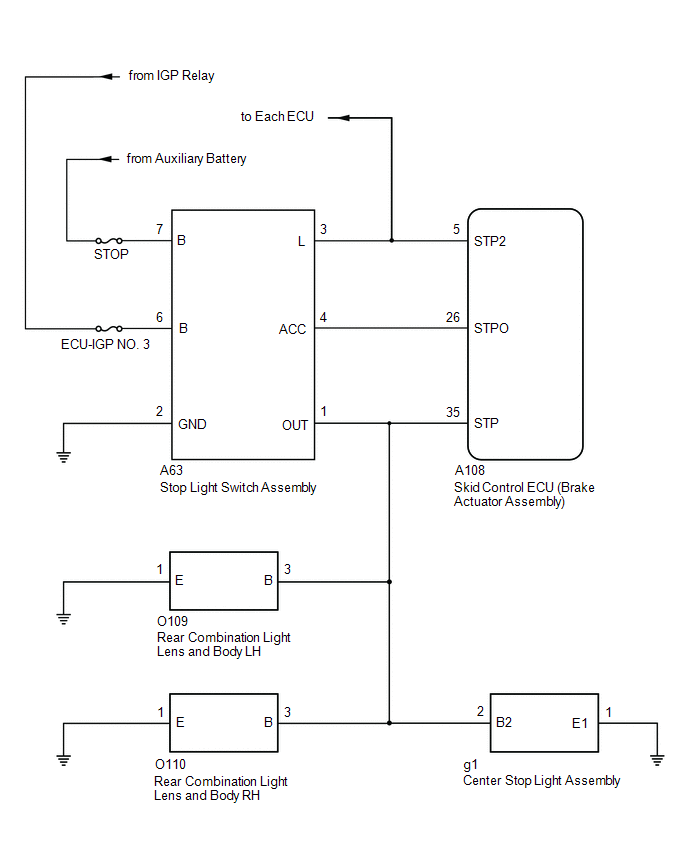
When any of the following conditions are met, the skid control ECU (brake actuator assembly) sets the drive output (STPO) ON which operates the stop light switch assembly and turns on the stop lights.
- Pre-collision brake is operating.
- The dynamic radar cruise control system is operating and is applying the brakes.
- Secondary collision brake is operating.
- The parking brake is engaged while the vehicle is being driven.
| DTC No. | Detection Item | DTC Detection Condition | Trouble Area | DTC Output from |
|---|---|---|---|---|
| C13807E | Stop Lamp Relay Actuator Stuck On | When the IGR terminal voltage exceeds 10 V and the +BS terminal voltage is 9.5 V or higher, stop light drive output (STPO) is OFF, STP is OFF and STP2 is ON continuously for 5 seconds or more. |
| Brake |
WIRING DIAGRAM
CAUTION / NOTICE / HINT
NOTICE:
After replacing the skid control ECU (brake actuator assembly), perform "Calibration".
Click here

PROCEDURE
| 1. | CHECK STOP LIGHT ILLUMINATION STATUS (FOR LED HEADLIGHT) |
(a) Make sure that there is no looseness at the locking part and the connecting part of the connectors.
OK:
The connector is securely connected.
(b) Disconnect the A63 stop light switch assembly connector.
(c) Check both the connector case and the terminals for deformation and corrosion.
OK:
No deformation or corrosion.
(d) Turn the ignition switch to ON.
(e) Check the illumination status of the brake lights.
| Result | Proceed to |
|---|---|
| The stop lights are illuminated | A |
| The stop lights are not illuminated | B |
| B |
 | GO TO STEP 7 |
|

| 2. | READ VALUE USING GTS (STOP LIGHT RELAY) |
(a) Turn the ignition switch off.
(b) Reconnect the A63 stop light switch assembly connector.
(c) Make sure that there is no looseness at the locking part and the connecting part of the connectors.
OK:
The connector is securely connected.
(d) Operate the GTS to check the Data List.
Chassis > Brake > Data List| Tester Display | Measurement Item | Range | Normal Condition | Diagnostic Note |
|---|---|---|---|---|
| Stop Light Relay | STP2 terminal input | OFF / ON | OFF: STP2 terminal input OFF ON: STP2 terminal input ON | HINT: The stop light state is determined using the voltage at terminal STP2 |
| Tester Display |
|---|
| Stop Light Relay |
(e) With the brake pedal released, check the value of Data List item "Stop Light Relay".
| Result | Proceed to |
|---|---|
| The value of Stop Light Relay is OFF | A |
| The value of Stop Light Relay is ON | B |
| A |
 | REPLACE STOP LIGHT SWITCH ASSEMBLY |
|

| 3. | READ VALUE USING GTS (STOP LIGHT RELAY) |
(a) Turn the ignition switch off.
(b) Make sure that there is no looseness at the locking part and the connecting part of the connectors.
OK:
The connector is securely connected.
(c) Disconnect the O109 rear combination light lens and body LH connector.
(d) Check both the connector case and the terminals for deformation and corrosion.
OK:
No deformation or corrosion.
(e) Operate the GTS to check the Data List.
Chassis > Brake > Data List| Tester Display | Measurement Item | Range | Normal Condition | Diagnostic Note |
|---|---|---|---|---|
| Stop Light Relay | STP2 terminal input | OFF / ON | OFF: STP2 terminal input OFF ON: STP2 terminal input ON | HINT: The stop light state is determined using the voltage at terminal STP2 |
| Tester Display |
|---|
| Stop Light Relay |
(f) With the brake pedal released, check the value of Data List item "Stop Light Relay".
| Result | Proceed to |
|---|---|
| The value of Stop Light Relay is OFF | A |
| The value of Stop Light Relay is ON | B |
| A |
 | GO TO LIGHTING SYSTEM |
|

| 4. | READ VALUE USING GTS (STOP LIGHT RELAY) |
(a) Turn the ignition switch off.
(b) Make sure that there is no looseness at the locking part and the connecting part of the connectors.
OK:
The connector is securely connected.
(c) Disconnect the O110 rear combination light lens and body RH connector.
(d) Check both the connector case and the terminals for deformation and corrosion.
OK:
No deformation or corrosion.
(e) Operate the GTS to check the Data List.
Chassis > Brake > Data List| Tester Display | Measurement Item | Range | Normal Condition | Diagnostic Note |
|---|---|---|---|---|
| Stop Light Relay | STP2 terminal input | OFF / ON | OFF: STP2 terminal input OFF ON: STP2 terminal input ON | HINT: The stop light state is determined using the voltage at terminal STP2 |
| Tester Display |
|---|
| Stop Light Relay |
(f) With the brake pedal released, check the value of Data List item "Stop Light Relay".
| Result | Proceed to |
|---|---|
| The value of Stop Light Relay is OFF | A |
| The value of Stop Light Relay is ON | B |
| A |
 | GO TO LIGHTING SYSTEM |
|

| 5. | READ VALUE USING GTS (STOP LIGHT RELAY) |
(a) Turn the ignition switch off.
(b) Make sure that there is no looseness at the locking part and the connecting part of the connectors.
OK:
The connector is securely connected.
(c) Disconnect the g1 center stop light assembly connector.
(d) Check both the connector case and the terminals for deformation and corrosion.
OK:
No deformation or corrosion.
(e) Operate the GTS to check the Data List.
Chassis > Brake > Data List| Tester Display | Measurement Item | Range | Normal Condition | Diagnostic Note |
|---|---|---|---|---|
| Stop Light Relay | STP2 terminal input | OFF / ON | OFF: STP2 terminal input OFF ON: STP2 terminal input ON | HINT: The stop light state is determined using the voltage at terminal STP2 |
| Tester Display |
|---|
| Stop Light Relay |
(f) With the brake pedal released, check the value of Data List item "Stop Light Relay".
| Result | Proceed to |
|---|---|
| The value of Stop Light Relay is OFF | A |
| The value of Stop Light Relay is ON | B |
| A |
 | REPLACE CENTER STOP LIGHT ASSEMBLY |
|

| 6. | CHECK HARNESS AND CONNECTOR (STOP LIGHT SWITCH ASSEMBLY - BRAKE ACTUATOR ASSEMBLY) |
(a) Turn the ignition switch off.
(b) Make sure that there is no looseness at the locking part and the connecting part of the connectors.
OK:
The connector is securely connected.
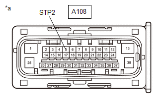
| (c) Disconnect the A108 skid control ECU (brake actuator assembly) connector. |
|
(d) Check both the connector case and the terminals for deformation and corrosion.
OK:
No deformation or corrosion.
(e) Turn the ignition switch to ON.
(f) Measure the voltage according to the value(s) in the table below.
Standard Voltage:
| Tester Connection | Condition | Specified Condition |
|---|---|---|
| A108-5 (STP2) - Body ground | Ignition switch ON | 0 V |
| OK |
 | REPLACE BRAKE ACTUATOR ASSEMBLY |
| NG |
 | REPAIR OR REPLACE HARNESS OR CONNECTOR |
| 7. | CHECK HARNESS AND CONNECTOR (STOP LIGHT SWITCH ASSEMBLY - BRAKE ACTUATOR ASSEMBLY) |
(a) Turn the ignition switch off.
(b) Make sure that there is no looseness at the locking part and the connecting part of the connectors.
OK:
The connector is securely connected.
(c) Disconnect the A108 skid control ECU (brake actuator assembly) connector.
(d) Check both the connector case and the terminals for deformation and corrosion.
OK:
No deformation or corrosion.
(e) Turn the ignition switch to ON.
(f) Measure the voltage according to the value(s) in the table below.
Standard Resistance:
| Tester Connection | Condition | Specified Condition |
|---|---|---|
| A63-4 (ACC) or A108-26 (STPO) - Body ground and other terminals | Always | 10 kΩ or higher |
| OK |
 | REPLACE BRAKE ACTUATOR ASSEMBLY |
| NG |
 | REPAIR OR REPLACE HARNESS OR CONNECTOR |
 Brake System Control Module "A" System Voltage System Voltage High (C137BA3)
DESCRIPTION If a malfunction is detected in the power supply circuit, the skid control ECU (brake actuator assembly) stores this DTC and the fail-safe function prohibits ABS operation...
 Stop Lamp Relay Actuator Stuck Off (C13807F)
DESCRIPTION Refer to DTC C13807E. Click here
DTC No. Detection Item DTC Detection Condition Trouble Area DTC Output from C13807F Stop Lamp Relay Actuator Stuck Off Either of the following is detected:
When the IGR terminal voltage exceeds 10 V and the +BS terminal voltage is from 9...
Other information:
Toyota Yaris XP210 (2020-2026) Owner's Manual: Split Folding the Seatback
By lowering the rear seatbacks the luggage compartment space can be expanded. WARNING Do not drive the vehicle with occupants on folded down seatbacks or in the luggage compartment. Putting occupants in the luggage compartment is dangerous because seat belts cannot be fastened which could lead to serious injury or death during sudden braking or a collision...
Toyota Yaris XP210 (2020-2026) Reapir and Service Manual: Components
COMPONENTS ILLUSTRATION *1 BENCH TYPE REAR SEAT CUSHION ASSEMBLY *2 REAR SEAT CUSHION LOCK HOOK *3 REAR SEAT INNER BELT ASSEMBLY LH *4 REAR SEAT INNER BELT ASSEMBLY RH Tightening torque for "Major areas involving basic vehicle performance such as moving/turning/stopping" : N*m (kgf*cm, ft...
Categories
- Manuals Home
- Toyota Yaris Owners Manual
- Toyota Yaris Service Manual
- How to use USB mode
- Engine & Hybrid System
- Key Battery Replacement
- New on site
- Most important about car
Key Suspend Function
If a key is left in the vehicle, the functions of the key left in the vehicle are temporarily suspended to prevent theft of the vehicle.
To restore the functions, press the unlock button on the functions-suspended key in the vehicle.