Toyota Yaris: Vehicle Stability Control System / Right Front Wheel Speed Sensor Circuit Short to Battery (C050612)
DESCRIPTION
Refer to DTC C05061F.
Click here

| DTC No. | Detection Item | DTC Detection Condition | Trouble Area | DTC Output from |
|---|---|---|---|---|
| C050612 | Right Front Wheel Speed Sensor Circuit Short to Battery | The speed sensor short signal is ON continuously for 0.5 seconds or more. |
| Brake |
WIRING DIAGRAM
Refer to DTC C05061F.
Click here

CAUTION / NOTICE / HINT
NOTICE:
-
After replacing the skid control ECU (brake actuator assembly), perform "Calibration".
Click here

-
After replacing or removing and installing a speed sensor, perform Dealer Mode (Signal Check) inspection to confirm that the speed sensors are operating correctly.
Click here

PROCEDURE
| 1. | CHECK HARNESS AND CONNECTOR (SENSOR GROUND CIRCUIT) |
(a) Make sure that there is no looseness at the locking part and the connecting part of the connectors.
OK:
The connector is securely connected.
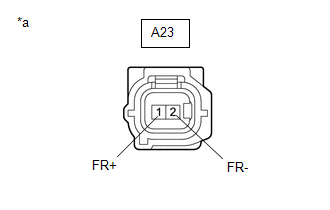
| (b) Disconnect the A23 front speed sensor RH connector. |
|
(c) Check both the connector case and the terminals for deformation and corrosion.
OK:
No deformation or corrosion.
(d) Turn the ignition switch to ON.
(e) Measure the voltage according to the value(s) in the table below.
Standard Voltage:
| Tester Connection | Condition | Specified Condition |
|---|---|---|
| A23-1 (FR+) - A23-2 (FR-) | Ignition switch ON | 11 to 14 V |
| OK |
 | REPLACE FRONT SPEED SENSOR RH |
|

| 2. | CHECK HARNESS AND CONNECTOR (SENSOR GROUND CIRCUIT) |
(a) Turn the ignition switch off.
| (b) Make sure that there is no looseness at the locking part and the connecting part of the connectors. OK: The connector is securely connected. |
|
(c) Disconnect the A108 skid control ECU (brake actuator assembly) connector.
(d) Check both the connector case and the terminals for deformation and corrosion.
OK:
No deformation or corrosion.
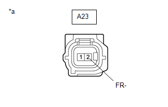
(e) Measure the voltage according to the value(s) in the table below.
Standard Voltage:
| Tester Connection | Condition | Specified Condition |
|---|---|---|
| A23-2 (FR-) - Body ground | Always | Below 1.5 V |
| NG |
 | REPAIR OR REPLACE HARNESS OR CONNECTOR |
|

| 3. | CHECK HARNESS AND CONNECTOR (FRONT SPEED SENSOR RH - BRAKE ACTUATOR ASSEMBLY) |
(a) Measure the resistance according to the value(s) in the table below.
Standard Resistance:
| Tester Connection | Condition | Specified Condition |
|---|---|---|
| A23-1 (FR+) or A108-31 (FR+) - A23-2 (FR-) or A108-30 (FR-) | Always | 10 kΩ or higher |
| OK |
 | REPLACE BRAKE ACTUATOR ASSEMBLY |
| NG |
 | REPAIR OR REPLACE HARNESS OR CONNECTOR |
 Left Front Wheel Speed Sensor Signal Has Too Many Pulses (C05003A,C05063A)
DESCRIPTION Refer to DTC C05001F. Click here
DTC No. Detection Item DTC Detection Condition Trouble Area DTC Output from C05003A Left Front Wheel Speed Sensor Signal Has Too Many Pulses When not in Dealer Mode (Signal Check) or Inspection Mode, the output of the speed sensor detected by the skid control ECU (brake actuator assembly) is too high for 5 second or more...
 Right Front Wheel Speed Sensor Circuit Short to Ground or Open (C050614)
DESCRIPTION Refer to DTC C05061F. Click here
DTC No. Detection Item DTC Detection Condition Trouble Area DTC Output from C050614 Right Front Wheel Speed Sensor Circuit Short to Ground or Open An open in the speed sensor signal circuit continues for 0...
Other information:
Toyota Yaris XP210 (2020-2026) Reapir and Service Manual: Engine Oil Pressure Too Low (P052400)
DESCRIPTION Refer to DTC P052012 DTC No. Detection Item DTC Detection Condition Trouble Area MIL Note P052400 Engine Oil Pressure Too Low When the engine is running, the oil pressure value output from the engine oil pressure and temperature sensor is less than the target value (1 trip detection logic)...
Toyota Yaris XP210 (2020-2026) Reapir and Service Manual: ECM/PCM Engine Off Timer Performance Signal Invalid (P261029)
DESCRIPTION The soak timer operates after the ignition switch is turned off. When a certain amount of time has elapsed after turning the ignition switch off, the soak timer activates the ECM to perform malfunction checks which can only be performed after the engine is stopped...
Categories
- Manuals Home
- Toyota Yaris Owners Manual
- Toyota Yaris Service Manual
- Brake System Control Module "A" System Voltage System Voltage Low (C137BA2)
- Engine Start Function When Key Battery is Dead
- Fuse Panel Description
- New on site
- Most important about car
Front Seat Belt Pretensioners
The front seat belt pretensioners are designed to deploy in moderate or severe frontal, near frontal collisions.
In addition, the pretensioners operate when a side collision or a rollover accident is detected. The pretensioners operate differently depending on what types of air bags are equipped. For more details about the seat belt pretensioner operation, refer to the SRS Air Bag Deployment Criteria.