Toyota Yaris: Vehicle Stability Control System / Right Front Wheel Speed Sensor Circuit Short to Ground or Open (C050614)
DESCRIPTION
Refer to DTC C05061F.
Click here

| DTC No. | Detection Item | DTC Detection Condition | Trouble Area | DTC Output from |
|---|---|---|---|---|
| C050614 | Right Front Wheel Speed Sensor Circuit Short to Ground or Open | An open in the speed sensor signal circuit continues for 0.5 seconds or more. |
| Brake |
WIRING DIAGRAM
Refer to DTC C05061F.
Click here

CAUTION / NOTICE / HINT
NOTICE:
-
After replacing the skid control ECU (brake actuator assembly), perform "Calibration".
Click here

-
After replacing or removing and installing a speed sensor, perform Dealer Mode (Signal Check) inspection to confirm that the speed sensors are operating correctly.
Click here

PROCEDURE
| 1. | READ VALUE USING GTS (FR SPEED OPEN) |
(a) Operate the GTS to check the Data List.
Chassis > Brake > Data List| Tester Display | Measurement Item | Range | Normal Condition | Diagnostic Note |
|---|---|---|---|---|
| FR Speed Open | Front speed sensor RH open detection | Under intermittent / Normal | Under intermittent: Momentary interruption detected Normal: Momentary interruption not detected | - |
| Tester Display |
|---|
| FR Speed Open |
(b) Select the line graph display.
(c) Check for any momentary interruption in the wire harness and connector.
Click here

OK:
Normal (There are no momentary interruptions.)
NOTICE:
Perform the above inspection before removing the sensor and connector.
| NG |
 | GO TO STEP 5 |
|

| 2. | READ VALUE USING GTS (FR WHEEL SPEED) |
(a) Operate the GTS to check the Data List.
Chassis > Brake > Data List| Tester Display | Measurement Item | Range | Normal Condition | Diagnostic Note |
|---|---|---|---|---|
| FR Wheel Speed | Front wheel speed sensor RH reading | Min.: 0.0 km/h (0.0 mph) Max.: 6553.5 km/h (4072 mph) | Vehicle stopped: 0.0 km/h (0.0 mph) | When driving at constant speed: No large fluctuations |
| Tester Display |
|---|
| FR Wheel Speed |
(b) Drive the vehicle and perform a road test.
(c) Check the speed value output from the speed sensor displayed on the GTS.
HINT:
Factors that affect the indicated vehicle speed include tire size, tire pressure, and tire wear. The speed indicated on the speedometer has an allowable margin of error. This can be tested using a speedometer tester (calibrated chassis dynamometer). For details about testing and the margin of error, see the reference chart.
Click here

OK:
The speed value output from the speed sensor displayed on the GTS is similar to the speed indicated on the speedometer.
| NG |
 | GO TO STEP 5 |
|

| 3. | CLEAR DTC |
(a) Operate the GTS to clear the codes.
Chassis > Brake > Clear DTCs(b) Press the DTC clear button.
(c) Turn the ignition switch off.
|

| 4. | RECONFIRM DTC |
(a) Based on the Freeze Frame Data and interview with the customer, attempt to reproduce the conditions when the malfunction occurred.
(b) Operate the GTS to read the DTCs.
Chassis > Brake > Trouble Codes(c) Check if the same DTC is output.
| Result | Proceed to |
|---|---|
| C050614 is not output | A |
| C050614 is output | B |
| A |
 | USE SIMULATION METHOD TO CHECK |
| B |
 | REPLACE BRAKE ACTUATOR ASSEMBLY |
| 5. | INSPECT HARNESS AND CONNECTOR (FRONT SPEED SENSOR RH - BRAKE ACTUATOR ASSEMBLY) |
(a) Turn the ignition switch off.
(b) Make sure that there is no looseness at the locking part and the connecting part of the connectors.
OK:
The connector is securely connected.
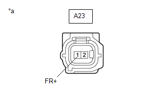
(c) Disconnect the A23 front speed sensor RH connector.
(d) Disconnect the A108 skid control ECU (brake actuator assembly) connector.
(e) Check both the connector case and the terminals for deformation and corrosion.
OK:
No deformation or corrosion.
(f) Measure the resistance according to the value(s) in the table below.
Standard Resistance:
| Tester Connection | Condition | Specified Condition |
|---|---|---|
| A23-1 (FR+) - A108-31 (FR+) | Always | Below 1 Ω |
| A23-1 (FR+) or A108-31 (FR+) - Body ground | Always | 10 kΩ or higher |
| A23-2 (FR-) - A108-30 (FR-) | Always | Below 1 Ω |
| A23-2 (FR-) or A108-30 (FR-) - Body ground | Always | 10 kΩ or higher |
| NG |
 | REPAIR OR REPLACE HARNESS OR CONNECTOR |
|

| 6. | INSPECT BRAKE ACTUATOR ASSEMBLY (SENSOR POWER SOURCE CIRCUIT) |
| (a) Reconnect the A108 skid control ECU (brake actuator assembly) connector. |
|
(b) Make sure that there is no looseness at the locking part and the connecting part of the connectors.
OK:
The connector is securely connected.
(c) Turn the ignition switch to ON.
(d) Measure the voltage according to the value(s) in the table below.
Standard Voltage:
| Tester Connection | Condition | Specified Condition |
|---|---|---|
| A23-1 (FR+) - Body ground | Ignition switch ON | 11 to 14 V |
| OK |
 | REPLACE FRONT SPEED SENSOR RH |
| NG |
 | REPLACE BRAKE ACTUATOR ASSEMBLY |
 Right Front Wheel Speed Sensor Circuit Short to Battery (C050612)
DESCRIPTION Refer to DTC C05061F. Click here
DTC No. Detection Item DTC Detection Condition Trouble Area DTC Output from C050612 Right Front Wheel Speed Sensor Circuit Short to Battery The speed sensor short signal is ON continuously for 0...
 Right Front Wheel Speed Sensor Circuit Intermittent (C05061F)
DESCRIPTION The speed sensor detects wheel speed and sends the appropriate signals to the skid control ECU (brake actuator assembly). These signals are used for brake control...
Other information:
Toyota Yaris XP210 (2020-2025) Reapir and Service Manual: Installation
INSTALLATION PROCEDURE 1. INSTALL REAR BUMPER ASSEMBLY (a) Connect the connector. Install in the Direction (b) Engage the claws to install the rear bumper assembly as shown in the illustration. (c) Engage the claws to install the rear bumper assembly as shown in the illustration...
Toyota Yaris XP210 (2020-2025) Owner's Manual: Windows
The windows can be opened/closed by operating the power window switches. When driving with only one of the rear windows open, your ears might experience a resonating sound. However, this does not indicate a problem. The sound can be reduced by slightly opening a front window or by changing the size of the rear window opening...
Categories
- Manuals Home
- Toyota Yaris Owners Manual
- Toyota Yaris Service Manual
- Fuel Gauge
- How to connect USB port/Auxiliary jack
- Fuse Panel Description
- New on site
- Most important about car
Keys

To use the auxiliary key, press the knob and pull out the auxiliary key from the smart key.
