Toyota Yaris: Sfi System / Terminals Of Ecm
TERMINALS OF ECM
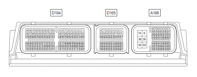
HINT:
The standard voltage, resistance and waveform between each pair of the ECM terminals is shown in the table below. The appropriate conditions for checking each pair of the terminals are also indicated. The result of checks should be compared with the standard voltage, resistance and waveform for each pair of the terminals as displayed in the Specified Condition column. The illustration above can be used as a reference to identify the ECM terminal locations.
| Terminal No. (Symbol) | Terminal Description | Condition | Specified Condition |
|---|---|---|---|
| A106-1(BATT) - A106-10(E1) | Auxiliary battery (for measuring auxiliary battery voltage and ECM memory) | Always | 11 to 14 V |
| A106-2(IGP) - A106-10(E1) | Ignition switch signal | Ignition switch ON | 11 to 14 V |
| A106-6(FPC) - A106-10(E1) | Fuel pump control | Engine stopped, ignition switch ON | 0 to 1.5 V |
| A106-8(CANH) - A106-10(E1) | CAN communication line | Engine stopped, ignition switch ON | Pulse generation (See waveform 1) |
| A106-9(+B) - A106-10(E1) | Power source of ECM | Ignition switch ON | 11 to 14 V |
| A106-10(E1) - Body ground | Ground | Always | Below 1 Ω |
| A106-13(IGR) - A106-10(E1) | Ignition signal | Ignition switch ON | 11 to 14 V |
| A106-15(MREL) - A106-10(E1) | EFI-MAIN NO. 1 relay operation signal | Engine stopped, ignition switch ON | 0 to 1.5 V |
| A106-16(NEO) - A106-10(E1) | Engine speed signal sent to other ECUs | Idling with warm engine | Pulse generation (See waveform 2) |
| A106-18(CANL) - A106-10(E1) | CAN communication line | Engine stopped, ignition switch ON | Pulse generation (See waveform 3) |
| A106-21(STP) - A106-10(E1) | Stop light switch assembly signal | Brake pedal depressed | 7.5 to 14 V |
| Brake pedal released | 0 to 1.5 V | ||
| A106-22(ST1-) - A106-10(E1) | Stop light switch assembly signal (opposite to STP terminal) | Ignition switch ON, brake pedal depressed | 0 to 1.5 V |
| Ignition switch ON, brake pedal released | 7.5 to 14 V | ||
| A106-23(NSW) - A106-10(E1) | Clutch start switch signal | Ignition switch ON, clutch pedal fully released | 11 to 14 V |
| Ignition switch ON, clutch pedal depressed | Below 3.0 V | ||
| A106-30(STA) - A106-10(E1) | Starter assembly signal | Cranking | 6 V or higher |
| A106-32(RFC) - A106-10(E1) | Cooling fan control signal | Ignition switch ON, A/C switch on (max cool) | Pulse generation (See waveform 4) |
| A106-34(IREL) - A106-10(E1) | EDU relay operation signal | Ignition switch ON | 0 to 1.5 V |
| A106-35(+B2) - A106-10(E1) | Power source of ECM | Ignition switch ON | 11 to 14 V |
| A106-36(E01) - Body ground | Ground | Always | Below 1 Ω |
| A106-39(KSW) - A106-10(E1) | Key in vehicle signal | Ignition switch ON | 0 to 3 V |
| A106-42(SPD) - A106-10(E1) | Vehicle speed signal from combination meter assembly | Driving at 20 km/h (12 mph) | Pulse generation (See waveform 5) |
| A106-45(EC) - Body ground | Ground | Always | Below 1 Ω |
| D104-19(+BD1) - A106-10(E1) | Power source of ECU (injector driver) | Ignition switch ON | 11 to 14 V |
| A106-54(E1D1) - Body ground | Ground | Always | Below 1 Ω |
| A106-55(VPA) - A106-56(EPA) | Accelerator pedal position sensor signal (for engine control) | Ignition switch ON, accelerator pedal fully released | 0.5 to 1.1 V |
| Ignition switch ON, accelerator pedal fully depressed | 2.6 to 4.5 V | ||
| A106-57(VCPA) - A106-56(EPA) | Power source of accelerator pedal position sensor (for VPA) | Engine stopped, ignition switch ON | 4.5 to 5.5 V |
| A106-58(VPA2) - A106-59(EPA2) | Accelerator pedal position sensor signal | Ignition switch ON, accelerator pedal fully released | 1.2 to 2.0 V |
| Ignition switch ON, accelerator pedal fully depressed | 3.4 to 4.75 V | ||
| A106-60(VCP2) - A106-59(EPA2) | Power source of accelerator pedal position sensor (for VPA2) | Engine stopped, ignition switch ON | 4.5 to 5.5 V |
| D104-4(M-) - A106-10(E1) | Throttle actuator operation signal (negative signal) | Idling with warm engine | Pulse generation (See waveform 6) |
| D104-3(M+) - A106-10(E1) | Throttle actuator operation signal (positive terminal) | Idling with warm engine | Pulse generation (See waveform 7) |
| D104-1(HA1B) - A106-10(E1) | Air fuel ratio sensor (sensor 2) heater operation signal | Engine stopped, ignition switch ON | 11 to 14 V |
| Idling with cold engine | Pulse generation (See waveform 8) | ||
| D104-2(HA1A) - A106-10(E1) | Air fuel ratio sensor (sensor 1) heater operation signal | Engine stopped, ignition switch ON | 11 to 14 V |
| Idling with cold engine | Pulse generation (See waveform 8) | ||
| D104-14(#2D-) - A106-10(E1) | Fuel injector assembly signal (No. 2 cylinder) | Idling with warm engine | Pulse generation (See waveform 9) |
| D104-33(#2D+) - A106-10(E1) | Fuel injector assembly signal (No. 2 cylinder) | Idling with warm engine | Pulse generation (See waveform 9) |
| D104-35(#3D+) - A106-10(E1) | Fuel injector assembly signal (No. 3 cylinder) | Idling with warm engine | Pulse generation (See waveform 9) |
| D104-16(#3D-) - A106-10(E1) | Fuel injector assembly signal (No. 3 cylinder) | Idling with warm engine | Pulse generation (See waveform 9) |
| D104-31(#1D+) - A106-10(E1) | Fuel injector assembly signal (No. 1 cylinder) | Idling with warm engine | Pulse generation (See waveform 9) |
| D104-12(#1D-) - A106-10(E1) | Fuel injector assembly signal (No. 1 cylinder) | Idling with warm engine | Pulse generation (See waveform 9) |
| D104-10(FP1-) - A106-10(E1) | Fuel pump assembly (for high pressure side) signal | Idling with warm engine | Pulse generation (See waveform 10) |
| D104-29(FP1+) - A106-10(E1) | Fuel pump assembly (for high pressure side) signal | Idling with warm engine | Pulse generation (See waveform 10) |
| D104-25(OE1+) - D104-26(OE1-) | Cam timing oil control solenoid assembly operation signal (for exhaust side) | Idling | Pulse generation (See waveform 11) |
| D104-27(OC1+) - D104-28(OC1-) | Cam timing oil control solenoid assembly operation signal (for intake side) | Idling | Pulse generation (See waveform 11) |
| D104-45(PRG) - A106-10(E1) | Purge VSV operation signal | Engine stopped, ignition switch ON | 11 to 14 V |
| Idling with warm engine, under purge control | Pulse generation (See waveform 12) | ||
| D104-70(IGT3) - A106-10(E1) | No. 3 ignition coil assembly signal (ignition signal) | Idling with warm engine | Pulse generation (See waveform 13) |
| D104-71(IGT2) - A106-10(E1) | No. 2 ignition coil assembly signal (ignition signal) | Idling with warm engine | Pulse generation (See waveform 13) |
| D104-72(IGT1) - A106-10(E1) | No. 1 ignition coil assembly signal (ignition signal) | Idling with warm engine | Pulse generation (See waveform 13) |
| D104-62(LIN) - A106-10(E1) | LIN communication line | Engine stopped, ignition switch ON | Pulse generation (See waveform 14) |
| D104-65(R) - A106-10(E1) | Reverse signal | Ignition switch ON, shift lever in R | 11 to 14 V |
| D104-84(VCVG) - A106-10(E1) | Power source of mass air flow meter sub-assembly (specific voltage) | Ignition switch ON | 4.8 to 5.2 V |
| D104-120(VCPF) - A106-10(E1) | Power source of fuel pressure sensor (for low pressure side) (specific voltage) | Ignition switch ON | 4.75 to 5.25 V |
| D104-87(VTA2) - D104-110(ETA) | Throttle position sensor signal (for sensor malfunction detection) | Ignition switch ON, accelerator pedal fully released | 2.1 to 3.1 V |
| Accelerator pedal fully depressed (engine running) | 4.6 to 5.0 V | ||
| D104-88(VCV1) - A106-10(E1) | Power source of camshaft position sensor (for intake camshaft) (specific voltage) | Ignition switch ON | 4.5 to 5.5 V |
| D104-90(VV1+) - D104-89(VV1-) | Camshaft position sensor (for intake camshaft) signal | Idling with warm engine | Pulse generation (See waveform 15) |
| D104-91(EV1+) - D104-114(EV1-) | Camshaft position sensor (for exhaust camshaft) signal | Idling with warm engine | Pulse generation (See waveform 15) |
| D104-92(NE+) - D104-115(NE-) | Crankshaft position sensor signal | Idling with warm engine | Pulse generation (See waveform 16) |
| D104-97(PR) - D104-73(EPR) | Fuel pressure sensor (for high pressure side) signal | Idling with warm engine | 0.5 to 4.5 V |
| D104-96(VCPR) - D104-73(EPR) | Power source of fuel pressure sensor (for high pressure side) (specific voltage) | Ignition switch ON | 4.75 to 5.25 V |
| D104-77(VCPE) - D104-78(EPEO) | Power source of engine oil pressure and temperature sensor (specific voltage) | Ignition switch ON | 4.5 to 5.5 V |
| D104-107(VG) - D104-83(E2G) | Mass air flow meter sub-assembly signal | Ignition switch ON | Pulse generation (See waveform 17) |
| D104-106(THA) - D104-83(E2G) | Intake air temperature sensor (mass air flow meter sub-assembly) signal | Idling, intake air temperature 0 to 80°C (32 to 176°F) | 0.5 to 3.4 V |
| D104-121(PFL) - D104-119(EPFL) | Fuel pressure sensor (for low pressure side) signal | Idling with warm engine | 0.57 to 4.88 V |
| D104-108(VTA1) - D104-110(ETA) | Throttle position sensor signal (for engine control) | Ignition switch ON, accelerator pedal fully released | 0.6 to 1.1 V |
| Accelerator pedal fully depressed (engine running) | 3.2 to 4.8 V | ||
| D104-109(VCTA) - D104-110(ETA) | Power source of throttle position sensor (specific voltage) | Ignition switch ON | 4.5 to 5.5 V |
| D104-111(KNK1) - D104-112(EKNK) | Knock control sensor signal | Engine speed maintained at 4000 rpm after warming up engine | Pulse generation (See waveform 18) |
| D104-113(VCE1) - A106-10(E1) | Power source of camshaft position sensor (for exhaust camshaft) (specific voltage) | Ignition switch ON | 4.5 to 5.5 V |
| D104-116(VCNE) - A106-10(E1) | Power source of crankshaft position sensor (specific voltage) | Ignition switch ON | 4.5 to 5.5 V |
| D104-117(A1B-) - A106-10(E1) | Air fuel ratio sensor (sensor 2) signal | Ignition switch ON | 1.17 to 4.49 V |
| D104-118(A1B+) - A106-10(E1) | Air fuel ratio sensor (sensor 2) signal | Ignition switch ON | 1.53 to 5.96 V |
| D104-98(PIM) - D104-76(EPIM) | No. 1 turbo pressure sensor signal | Ignition switch ON | 3.0 to 4.5 V |
| D104-75(VCPM) - D104-76(EPIM) | Power source of No.1 turbo pressure sensor (specific voltage) | Ignition switch ON | 4.75 to 5.25 V |
| D104-100(PEO) - D104-78(EPEO) | Engine oil pressure sensor (engine oil pressure and temperature sensor) signal | Idling with warm engine | 0.5 to 4.5 V |
| D104-101(THEO) - D104-78(EPEO) | Engine oil pressure sensor (engine oil pressure and temperature sensor) signal | Ignition switch ON | 0.54 to 4.86 V |
| D104-129(THW) - D104-130(ETHW) | Engine coolant temperature sensor signal | Idling, engine coolant temperature 75 to 100°C (167 to 212°F) | 0.2 to 1.0 V |
| D104-18(+BD3) - A106-10(E1) | Power source of ECU (injector driver) | Ignition switch ON | 11 to 14 V |
| D104-38(+BD2) - A106-10(E1) | Power source of ECU (injector driver) | Ignition switch ON | 11 to 14 V |
| D104-49(AICV) - A106-10(E1) | Vacuum switching valve for air intake control valve operation signal | Ignition switch ON | 11 to 14 V |
| D104-20(ABV) - A106-10(E1) | Air by-pass valve assembly operation signal | Engine stopped, ignition switch ON | 11 to 14 V |
| Air by-pass valve assembly operating | Below 1.5 V | ||
| D104-94(A1A-) - A106-10(E1) | Air fuel ratio sensor (sensor 1) signal | Ignition switch ON | 1.17 to 4.49 V |
| D104-95(A1A+) - A106-10(E1) | Air fuel ratio sensor (sensor 1) signal | Ignition switch ON | 1.53 to 5.96 V |
| D104-99(THIM) - A106-10(E1) | Intake air temperature sensor (No. 1 turbo pressure sensor) signal | Idling with warm engine | 0 to 5.25 V |
| D104-82(VCPC) - D104-81(EPIC) | Power source of Vacuum sensor (specific voltage) | Ignition switch ON | 4.5 to 5.5 V |
| D104-105(PIC) - D104-81(EPIC) | Vacuum sensor signal | Idling with warm engine | 1.0 to 4.5 V |
| D104-80(VPTA) - D104-79(EPTA) | Power source of No.2 turbo pressure sensor (specific voltage) | Ignition switch ON | 4.5 to 5.5 V |
| D104-103(PTA) - D104-79(EPTA) | No. 2 turbo pressure sensor signal | Idling with warm engine | 1.0 to 4.5 V |
| D104-102(THTA) - A106-10(E1) | Intake air temperature sensor (No. 2 turbo pressure sensor) signal | Idling with warm engine | 0 to 5.25 V |
| D104-50(#30) - A106-10(E1) | Port fuel injector assembly signal (No. 3 cylinder) | Idling with warm engine (Data List item "Injection Mode" displaying "Port") | Pulse generation (See waveform 19) |
| D104-51(#20) - A106-10(E1) | Port fuel injector assembly signal (No. 2 cylinder) | Idling with warm engine (Data List item "Injection Mode" displaying "Port") | Pulse generation (See waveform 19) |
| D104-52(#10) - A106-10(E1) | Port fuel injector assembly signal (No. 1 cylinder) | Idling with warm engine (Data List item "Injection Mode" displaying "Port") | Pulse generation (See waveform 19) |
| D104-21(WGV+) - A106-10(E1) | Vacuum regulating valve assembly operation signal | Vacuum regulating valve assembly operating | Pulse generation |
| D104-22(WGV-) - A106-10(E1) | Vacuum regulating valve assembly operation signal | Vacuum regulating valve assembly operating | Pulse generation |
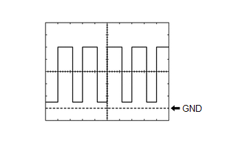
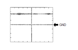
WAVEFORM 1
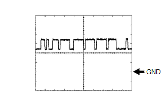 CAN Communication Signal (Reference)
 | ECM Terminal Name | Between CANH and E1 |
| Tester Range | 1 V/DIV., 10 μs./DIV. |
| Condition | Engine stopped, ignition switch ON |
HINT:
The waveform varies depending on the CAN communication signal.
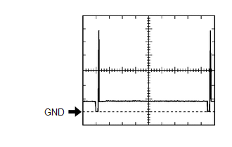
WAVEFORM 2
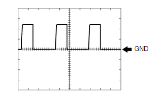 Engine Speed Signal
 | ECM Terminal Name | Between NEO and E1 |
| Tester Range | 5 V/DIV., 2 ms./DIV. |
| Condition | Idling with warm engine |
HINT:
The wavelength becomes shorter as the engine speed increases.
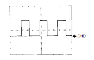
WAVEFORM 3
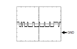 CAN Communication Signal (Reference)
 | ECM Terminal Name | Between CANL and E1 |
| Tester Range | 1 V/DIV., 10 μs./DIV. |
| Condition | Engine stopped, ignition switch ON |
HINT:
The waveform varies depending on the CAN communication signal.
WAVEFORM 4
 Cooling Fan Control Signal
 | ECM Terminal Name | Between RFC and E1 |
| Tester Range | 1 V/DIV., 20 ms/DIV. |
| Condition | Ignition switch ON, A/C switch on (max cool) |
HINT:
The duty ratio varies depending on the engine coolant temperature.
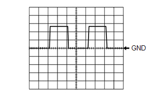
WAVEFORM 5
 Vehicle Speed Signal
 | ECM Terminal Name | Between SPD and E1 |
| Tester Range | 2 V/DIV., 20 ms./DIV. |
| Condition | Driving at 20 km/h (12 mph) |
HINT:
The wavelength becomes shorter as the vehicle speed increases.
WAVEFORM 6
 Throttle Actuator Operation Signal (Negative Terminal)
 | ECM Terminal Name | Between M- and E1 |
| Tester Range | 5 V/DIV., 1 ms./DIV. |
| Condition | Idling with warm engine |
HINT:
The duty ratio varies depending on the throttle actuator operation.
WAVEFORM 7
 Throttle Actuator Operation Signal (Positive Terminal)
 | ECM Terminal Name | Between M+ and E1 |
| Tester Range | 5 V/DIV., 1 ms./DIV. |
| Condition | Idling with warm engine |
HINT:
The duty ratio varies depending on the throttle actuator operation.
WAVEFORM 8
 Air Fuel Ratio Sensor Heater Operation Signal
 | ECM Terminal Name | Between HA1A and E1 Between HA1B and E1 |
| Tester Range | 5 V/DIV., 10 ms./DIV. |
| Condition | Idling with cold engine |
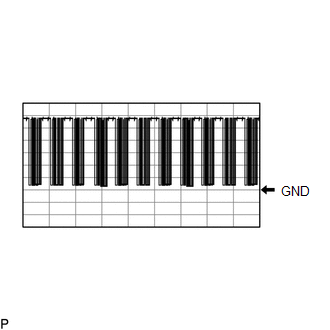
WAVEFORM 9
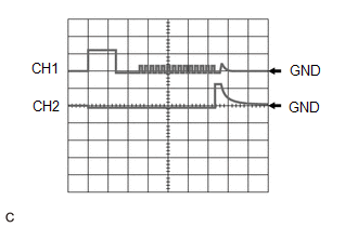 No. 1 (to No. 3) Fuel Injector Assembly Signal
 | ECM Terminal Name | CH1: Between #1D+ and E1 CH2: Between #1D- and E1 |
| CH1: Between #2D+ and E1 CH2: Between #2D- and E1 | |
| CH1: Between #3D+ and E1 CH2: Between #3D- and E1 | |
| Tester Range | 50 V/DIV., 200 μs./DIV. |
| Condition | Idling with warm engine. |
WAVEFORM 10
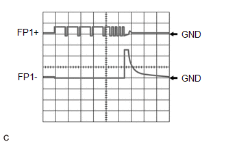 Fuel Pump Assembly (for High Pressure Side) Signal
 | ECM Terminal Name | CH1: Between FP1+ and E1 CH2: Between FP1- and E1 |
| Tester Range | 20 V/DIV., 500 μs./DIV. |
| Condition | Idling with warm engine, Data List item "Injection Mode" displaying "Direct" |
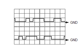
WAVEFORM 11
 Cam Timing Oil Control Solenoid Assembly Operation Signal
 | ECM Terminal Name | Between OC1+ and OC1- Between OE1+ and OE1- |
| Tester Range | 5 V/DIV., 1 ms./DIV. |
| Condition | Idling |
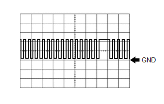
WAVEFORM 12
 Purge VSV Operation Signal
 | ECM Terminal Name | Between PRG and E1 |
| Tester Range | 10 V/DIV., 20 ms./DIV. |
| Condition | Idling with warm engine, under purge control |
HINT:
If the waveform is not similar to the illustration, check the waveform again after idling for 10 minutes or more.
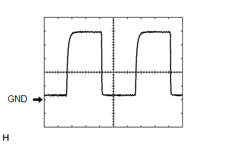
WAVEFORM 13
 Ignition Coil Assembly Signal (IGT Signal)
 | ECM Terminal Name | Between IGT (1 to 3) and E1 |
| Tester Range | 5 V/DIV, 20 ms/DIV |
| Condition | Idling with warm engine |
HINT:
The wavelength becomes shorter as the engine speed increases.
WAVEFORM 14
 LIN Communication Signal (Reference)
 | ECM Terminal Name | Between LIN and E1 |
| Tester Range | 2 V/DIV., 10 ms./DIV. |
| Condition | Idling with warm engine |
WAVEFORM 15
 Camshaft Position Sensor Signal
 | ECM Terminal Name | CH1: Between VV1+ and VV1- CH2: Between EV1+ and EV1- |
| Tester Range | 5 V/DIV., 20 ms./DIV. |
| Condition | Idling with warm engine |
HINT:
The wavelength becomes shorter as the engine speed increases.
WAVEFORM 16
 Crankshaft Position Sensor Signal
 | ECM Terminal Name | Between NE+ and NE- |
| Tester Range | 2 V/DIV., 20 ms./DIV. |
| Condition | Idling with warm engine |
HINT:
The wavelength becomes shorter as the engine speed increases.
WAVEFORM 17
 Mass Air Flow Meter Sub-assembly Signal
 | ECM Terminal Name | Between VG and E2G |
| Tester Range | 1 V/DIV., 100 μs./DIV. |
| Condition | Ignition switch ON |
WAVEFORM 18
 Knock Control Sensor Signal
 | ECM Terminal Name | Between KNK1 and EKNK |
| Tester Range | 1 V/DIV., 1 ms./DIV. |
| Condition | Engine speed maintained at 4000 rpm after warming up the engine |
HINT:
- The wavelength becomes shorter as the engine speed increases.
- The waveforms and amplitudes displayed differ slightly depending on the vehicle.
WAVEFORM 19
 Port Fuel Injector Assembly Signal
 | ECM Terminal Name | Between #10 (to #30) and E1 |
| Tester Range | 20 V/DIV., 20 ms./DIV. |
| Condition | Idling with warm engine (Data List item "Injection Mode" displaying "Port") |
HINT:
- The wavelength becomes shorter as the engine speed increases.
- When the port injection injectors are operating, Port is displayed for Injection Mode of the Data List.
 Problem Symptoms Table
PROBLEM SYMPTOMS TABLE HINT:
Use the table below to help determine the cause of problem symptoms. If multiple suspected areas are listed, the potential causes of the symptoms are listed in order of probability in the "Suspected Area" column of the table...
 Diagnosis System
DIAGNOSIS SYSTEM EURO-OBD (EUROPEAN SPEC)
When troubleshooting Europe On-Board Diagnostic (Euro-OBD) vehicles, an OBD scan tool (complying with ISO 15765-4) must be connected to the vehicle...
Other information:
Toyota Yaris XP210 (2020-2026) Reapir and Service Manual: Fuel Tank Cap
I..
Toyota Yaris XP210 (2020-2026) Reapir and Service Manual: Customize Parameters
CUSTOMIZE PARAMETERS CUSTOMIZE LIGHTING SYSTEM (INT) NOTICE: When the customer requests a change in a function, first make sure that the function can be customized. Be sure to make a note of the current settings before customizing. When troubleshooting a function, first make sure that the function is set to the default setting...
Categories
- Manuals Home
- Toyota Yaris Owners Manual
- Toyota Yaris Service Manual
- Brake System Control Module "A" System Voltage System Voltage Low (C137BA2)
- Fuse Panel Description
- Key Battery Replacement
- New on site
- Most important about car
Key Suspend Function
If a key is left in the vehicle, the functions of the key left in the vehicle are temporarily suspended to prevent theft of the vehicle.
To restore the functions, press the unlock button on the functions-suspended key in the vehicle.