Toyota Yaris: Sfi System / Brake Switch "B" Circuit Short to Battery (P070312)
DESCRIPTION
The stop light switch assembly is part of a duplex system that transmits two signals: STP and ST1-. These two signals are used by the ECM to monitor whether or not the brake system is working properly. This DTC indicates that the stop light switch assembly remains on. When the stop light switch assembly remains on during "STOP and GO" driving, the ECM interprets this as a fault in the stop light switch assembly. The ECM stores the DTC.
| DTC No. | Detection Item | DTC Detection Condition | Trouble Area | MIL | Note |
|---|---|---|---|---|---|
| P070312 | Brake Switch "B" Circuit Short to Battery | The stop light switch assembly remains on even when vehicle repeats 5 cycles of STOP (less than 3 km/h [1.86 mph]) and GO (30 km/h [18.65 mph] or more) (2 trip detection logic). |
| - | SAE: P0724 |
MONITOR DESCRIPTION
This DTC indicates that the stop light switch assembly remains on. When the stop light switch assembly remains on during "STOP and GO" driving, the ECM interprets this as a fault in the stop light switch assembly. The ECM stores the DTC. The vehicle must STOP (less than 3 km/h [1.86 mph]) and GO (30 km/h [18.65 mph] or more) 5 times during 2 driving cycles, in order to detect a malfunction.
MONITOR STRATEGY
| Required Sensors/Components (Main) | Stop light switch assembly |
| Required Sensors/Components (Related) | Speed sensor |
| Frequency of Operation | Continuous |
CONFIRMATION DRIVING PATTERN
- Connect the GTS to the DLC3.
- Turn the ignition switch to ON.
- Turn the GTS on.
- Clear the DTCs (even if no DTCs are stored, perform the clear DTC procedure).
- Turn the ignition switch off and wait for at least 30 seconds.
- Turn the ignition switch to ON.
- Turn the GTS on.
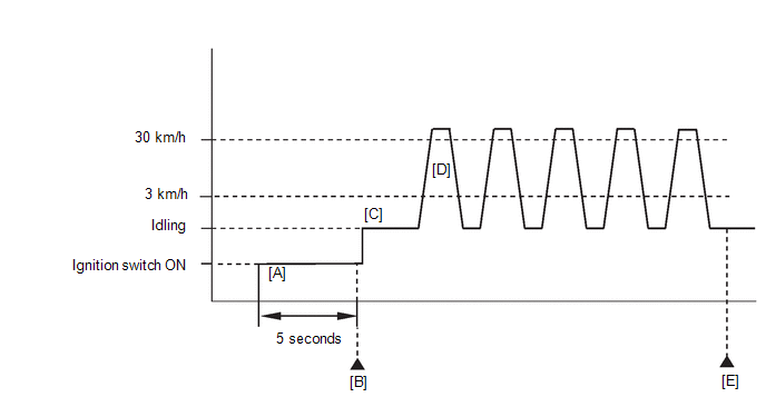
- Wait 5 seconds [A].
- Enter the following menus: Powertrain / Engine / Trouble Codes [B].
-
Read the pending DTCs.
HINT:
- If a pending DTC is output, the system is malfunctioning.
- If a pending DTC is not output, perform the following procedure.
- Enter the following menus: Powertrain / Engine / Utility / All Readiness.
- Input the DTC: P070312.
-
Check the DTC judgment result.
GTS Display
Description
NORMAL
- DTC judgment completed
- System normal
ABNORMAL
- DTC judgment completed
- System abnormal
INCOMPLETE
- DTC judgment not completed
- Perform driving pattern after confirming DTC enabling conditions
HINT:
- If the judgment result is NORMAL, the system is normal.
- If the judgment result is ABNORMAL, the system has a malfunction.
- If the judgment result is INCOMPLETE, perform steps [C] through [E].
- Start the engine [C].
-
Accelerate the vehicle to 30 km/h (18.65 mph) or more, depress the brake pedal and decelerate the vehicle to 3 km/h (1.86 mph) or less [D]. Repeat step [D] 5 times.
CAUTION:
When performing the confirmation driving pattern, obey all speed limits and traffic laws.
- Enter the following menus: Powertrain / Engine / Trouble Codes [E].
-
Read the pending DTCs.
HINT:
- If a pending DTC is output, the system is malfunctioning.
- If a pending DTCs are not output, perform the following procedure.
- Enter the following menus: Powertrain / Engine / Utility / All Readiness.
- Input the DTC: P070312.
-
Check the DTC judgment result.
GTS Display
Description
NORMAL
- DTC judgment completed
- System normal
ABNORMAL
- DTC judgment completed
- System abnormal
INCOMPLETE
- DTC judgment not completed
- Perform driving pattern after confirming DTC enabling conditions
HINT:
- If the judgment result is NORMAL, the system is normal.
- If the judgment result is ABNORMAL, the system has a malfunction.
WIRING DIAGRAM
Refer to DTC P05042B.
Click here

CAUTION / NOTICE / HINT
NOTICE:
Inspect the fuses for circuits related to this system before performing the following procedure.
HINT:
-
Using the GTS, the Data List item "Stop Light SW" can be read.
Click here

- Read Freeze Frame Data using the GTS. The ECM records vehicle and driving condition information as Freeze Frame Data the moment a DTC is stored. When troubleshooting, Freeze Frame Data can help determine if the vehicle was moving or stationary, if the engine was warmed up or not, if the air fuel ratio was lean or rich, and other data from the time the malfunction occurred.
PROCEDURE
| 1. | READ VALUE USING GTS (STOP LIGHT SW) |
(a) Enter the following menus.
Powertrain > Engine > Data List| Tester Display |
|---|
| Stop Light SW |
(b) Read the Data List displayed on the GTS.
OK:
| GTS Display | Measurement Item/Range (Display) | Normal Condition |
|---|---|---|
| Stop Light SW | Stop light switch assembly status: ON or OFF |
|
| OK |
 | CHECK FOR INTERMITTENT PROBLEMS |
|

| 2. | CHECK STOP LIGHT SWITCH ASSEMBLY INSTALLATION |
(a) Check the stop light switch installation.
Click here

OK:
Stop light switch is installed correctly.
| NG |
 | SECURELY REINSTALL STOP LIGHT SWITCH ASSEMBLY |
|

| 3. | CHECK TERMINAL VOLTAGE (STP VOLTAGE) |
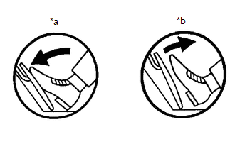
| *a | Brake Pedal Depressed |
| *b | Brake Pedal Released |
(a) Disconnect the ECM connector.
(b) Measure the voltage according to the value(s) in the table below.
Standard Voltage:
| Tester Connection | Brake Pedal Operation | Specified Condition |
|---|---|---|
| A106-21(STP) - Body ground | Released | Below 1.5 V |
| Depressed | 7.5 to 14 V |
HINT:
If there is a short in the STP terminal circuit, there may be a malfunction in the circuit of a connected ECU.
| OK |
 | REPLACE ECM |
|

| 4. | CHECK HARNESS AND CONNECTOR (STOP LIGHT SWITCH ASSEMBLY - ECM) |
(a) Disconnect the stop light switch assembly connector.
(b) Disconnect the ECM connector.
(c) Measure the resistance according to the value(s) in the table below.
Standard Resistance:
| Tester Connection | Condition | Specified Condition |
|---|---|---|
| A63-3(L) or A106-21(STP) - Other terminals | Always | 10 kΩ or higher |
| OK |
 | REPLACE STOP LIGHT SWITCH ASSEMBLY |
| NG |
 | REPAIR OR REPLACE HARNESS OR CONNECTOR |
 Actuator Supply Voltage "A" Stuck On (P06579E)
MONITOR DESCRIPTION The ECM monitors the output voltage to the throttle actuator. This self-check ensures that the ECM is functioning properly. The output voltage is usually 0 V when the ignition switch is turned off...
 Fuel Rail Pressure Sensor (Low) Circuit Short to Ground (P107A11)
DESCRIPTION
The No. 2 fuel pressure sensor (for low pressure side) replaces the fuel pressure with electrical signals and outputs them to the ECM. The ECM controls the optimal fuel pressure for the operation conditions to reduce the fuel pump power consumption and improve fuel economy...
Other information:
Toyota Yaris XP210 (2020-2026) Reapir and Service Manual: Vehicle Control History
VEHICLE CONTROL HISTORY NOTICE: Vehicle control history may be recorded due to the replacement or repair of related parts. CHECK VEHICLE CONTROL HISTORY (FRONT CAMERA SYSTEM) (a) According to the display on the GTS, check the vehicle control history. Chassis > Front Recognition Camera > Utility Tester Display Vehicle Control History (RoB) Vehicle Control History (RoB) Multi-information Display Code Tester Display Description Diagnostic Note Pre-Collision System Malfunction Visit Your Dealer X2000 Yaw Rate Sensor Malfunction The forward recognition camera received a yaw rate sensor malfunction signal from the skid control ECU (brake actuator assembly)...
Toyota Yaris XP210 (2020-2026) Reapir and Service Manual: Disassembly
DISASSEMBLY PROCEDURE 1. REMOVE LOWER DEFROSTER NOZZLE ASSEMBLY (a) Disengage the claws and guides to remove the lower defroster nozzle assembly. 2. REMOVE COOLER PIPE GROMMET (a) Remove the cooler pipe grommet. 3. REMOVE COOLER EXPANSION VALVE (a) Using a 4 mm hexagon socket wrench, remove the 2 hexagon bolts and cooler expansion valve...
Categories
- Manuals Home
- Toyota Yaris Owners Manual
- Toyota Yaris Service Manual
- Brake System Control Module "A" System Voltage System Voltage Low (C137BA2)
- How to connect USB port/Auxiliary jack
- G16e-gts (engine Mechanical)
- New on site
- Most important about car
Fuel-Filler Lid and Cap
WARNING
When removing the fuel-filler cap, loosen the cap slightly and wait for any hissing to stop, then remove it
Fuel spray is dangerous. Fuel can burn skin and eyes and cause illness if ingested. Fuel spray is released when there is pressure in the fuel tank and the fuel-filler cap is removed too quickly.