Toyota Yaris: Clutch Unit / Removal
REMOVAL
CAUTION / NOTICE / HINT
The necessary procedures (adjustment, calibration, initialization or registration) that must be performed after parts are removed and installed, or replaced during the cover and disc clutch set removal/installation are shown below.
Necessary Procedure After Parts Removed/Installed/Replaced| Replaced Part or Performed Procedure | Necessary Procedure | Effect/Inoperative Function when Necessary Procedure not Performed | Link |
|---|---|---|---|
| Front wheel alignment adjustment | ECU Data Initialization | Active torque split AWD system |
|
| Calibration |
|
|


NOTICE:
When the manual transaxle assembly is removed, be sure to use a new clutch release cylinder with bearing assembly and new installation bolts. Removal of the manual transaxle assembly allows the compressed clutch release cylinder with bearing assembly to return to its original position. Dust from the moving section may damage the seal of the clutch release cylinder with bearing assembly, possibly causing clutch fluid leaks.
HINT:
When the cable is disconnected / reconnected to the auxiliary battery terminal, systems temporarily stop operating. However, each system has a function that completes learning the first time the system is used.
-
Learning completes when vehicle is driven
Effect/Inoperative Function When Necessary Procedures are not Performed
Necessary Procedures
Link
Lane tracing assist system
Drive the vehicle straight ahead at 35 km/h (22 mph) or more for 5 second or more.

Pre-collision system
Stop and start system
Drive the vehicle until stop and start control is permitted (approximately 5 to 60 minutes)

-
Learning completes when vehicle is operated normally
Effect/Inoperative Function When Necessary Procedures are not Performed
Necessary Procedures
Link
Power door lock control system
- Back door opener
Perform door unlock operation with door control switch or electrical key transmitter sub-assembly switch.

Air conditioning system
After the ignition switch is turned to ON, the servo motor standard position is recognized.
-
PROCEDURE
1. REMOVE MANUAL TRANSAXLE ASSEMBLY
Click here

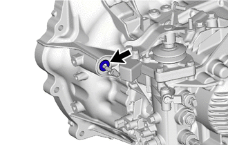
2. REMOVE BLEEDER CLUTCH RELEASE TUBE
| (a) Using a 10 mm union nut wrench, disconnect the bleeder clutch release tube from the clutch release bleeder sub-assembly. |
|
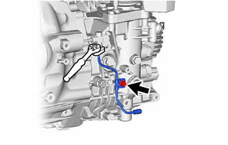
(b) Remove the bolt and bleeder clutch release tube from the manual transaxle assembly.
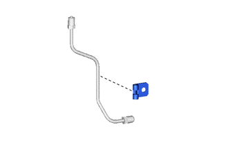
| (c) Remove the clamp from the bleeder clutch release tube. |
|
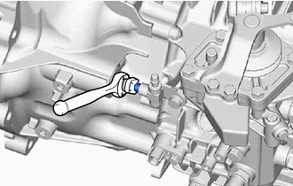
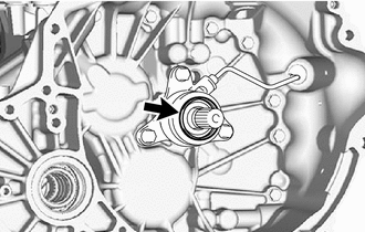
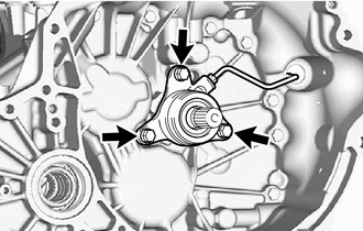
3. REMOVE CLUTCH RELEASE BLEEDER SUB-ASSEMBLY
| (a) Using a 10 mm union nut wrench, disconnect the clutch release cylinder to bleeder tube from the clutch release bleeder sub-assembly. |
|
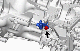
| (b) Remove the bolt and clutch release bleeder sub-assembly from the manual transaxle assembly. |
|
4. REMOVE CLUTCH RELEASE BEARING PLATE
| (a) Remove the clutch release bearing plate from the clutch release cylinder with bearing assembly. NOTICE: When removing the manual transaxle assembly, the clutch release bearing plate could fall out. |
|
5. REMOVE CLUTCH RELEASE CYLINDER WITH BEARING ASSEMBLY
| (a) Remove the clutch tube boot from the manual transaxle assembly. |
|
| (b) Remove the 3 bolts and clutch release cylinder with bearing assembly together with clutch release cylinder to bleeder tube from the manual transaxle assembly. |
|
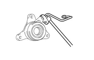
6. REMOVE CLUTCH RELEASE CYLINDER TO BLEEDER TUBE
(a) Mount the clutch release cylinder with bearing assembly in a soft jaw vise.
| (b) Using a 10 mm union nut wrench, remove the clutch release cylinder to bleeder tube from the clutch release cylinder with bearing assembly. |
|
7. REMOVE COVER AND DISC CLUTCH SET
| (a) Put matchmarks on the clutch cover assembly and the flywheel sub-assembly. |
|
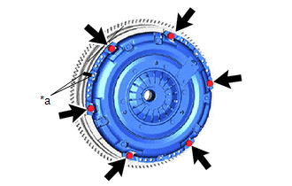
(b) Loosen each bolt 180° at a time until the spring tension is released.
(c) Remove the 6 bolts and pull off the cover and disc clutch set.
NOTICE:
- Do not drop the clutch disc assembly.
- Keep the lined part of the clutch disc assembly, the pressure plate, and the surface of the flywheel sub-assembly away from oil and foreign matter.
 Components
COMPONENTS ILLUSTRATION
*1 COVER AND DISC CLUTCH SET *2 MANUAL TRANSAXLE ASSEMBLY *3 CLUTCH RELEASE CYLINDER WITH BEARING ASSEMBLY *4 CLUTCH TUBE BOOT *5 CLUTCH RELEASE CYLINDER TO BLEEDER TUBE *6 CLUTCH RELEASE BLEEDER SUB-ASSEMBLY *7 BLEEDER CLUTCH RELEASE TUBE *8 CLAMP *9 CLUTCH RELEASE BEARING PLATE - -
Tightening torque for "Major areas involving basic vehicle performance such as moving/turning/stopping": N*m (kgf*cm, ft...
 Inspection
INSPECTION PROCEDURE 1. INSPECT CLUTCH DISC ASSEMBLY (a) Using a vernier caliper, measure the rivet head depth. Minimum Rivet Head Depth: 0.3 mm (0...
Other information:
Toyota Yaris XP210 (2020-2026) Owner's Manual: Driving Tips
Passing For extra power when passing another vehicle or climbing steep grades, depress the accelerator fully. The transaxle will shift to a lower gear, depending on vehicle speed. Some models: The accelerator pedal may initially feel heavy as it is being depressed, then feel lighter as it is depressed further...
Toyota Yaris XP210 (2020-2026) Reapir and Service Manual: Air Inlet Damper Control Servo Motor Actuator Stuck Off (B143B7F)
DESCRIPTION The No. 1 blower damper servo sub-assembly sends pulse signals to inform the air conditioning amplifier assembly of the damper position. The air conditioning amplifier assembly activates the motor (normal or reverse) based on these signals to move the air inlet damper to the appropriate position, which controls the air inlet switching...
Categories
- Manuals Home
- Toyota Yaris Owners Manual
- Toyota Yaris Service Manual
- G16e-gts (engine Mechanical)
- Brake System Control Module "A" System Voltage System Voltage Low (C137BA2)
- Diagnostic Trouble Code Chart
- New on site
- Most important about car
Refueling
Before refueling, close all the doors, windows, and the liftgate/trunk lid, and switch the ignition OFF.
To open the fuel-filler lid, pull the remote fuel-filler lid release.
