Toyota Yaris: Air Conditioning System / Air Inlet Damper Control Servo Motor Actuator Stuck Off (B143B7F)
DESCRIPTION
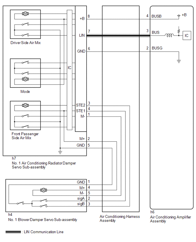
The No. 1 blower damper servo sub-assembly sends pulse signals to inform the air conditioning amplifier assembly of the damper position. The air conditioning amplifier assembly activates the motor (normal or reverse) based on these signals to move the air inlet damper to the appropriate position, which controls the air inlet switching.
The air conditioning amplifier assembly communicates with the servo through a communication/driver IC and wiring assembly called the air conditioning harness assembly.
| DTC No. | Detection Item | DTC Detection Condition | Trouble Area | Memory |
|---|---|---|---|---|
| B143B7F | Air Inlet Damper Control Servo Motor Actuator Stuck Off | Diagnosis Condition:
Malfunction Status:
Detection Time:
|
| Memorized |
| Vehicle Condition | |||
|---|---|---|---|
| Pattern 1 | Pattern 2 | ||
| Diagnosis Condition | No. 1 blower damper servo sub-assembly operating | ○ | ○ |
| Malfunction | Damper servo operation request signals are output but the damper position sensor value does not change | ○ | - |
| Damper servo operation request signals are output but the damper position sensor value is abnormal | - | ○ | |
| Detection Time | Continuously for 30 seconds or more | Continuously for 30 seconds or more | |
| Trip Count | 1 trip | 1 trip | |
HINT:
If the conditions of either of these patterns are detected, a DTC will be stored
WIRING DIAGRAM
CAUTION / NOTICE / HINT
NOTICE:
-
This DTC is also output for the damper link, damper lock, etc. Before performing inspection, perform servomotor initialization and check that there are no mechanical malfunctions.
Click here

-
This DTC is also output when servomotor initialization has failed. When servomotor initialization has failed, repair any malfunctions and perform servomotor initialization again.
Click here

PROCEDURE
| 1. | CHECK FOR DTC |
(a) Check for DTCs.
Body Electrical > Air Conditioner > Trouble Codes| Result | Proceed to |
|---|---|
| B14037F, B14067F and B143B7F are output | A |
| Only B143B7F is output | B |
| A |
 | REPLACE NO. 1 AIR CONDITIONING RADIATOR DAMPER SERVO SUB-ASSEMBLY |
|

| 2. | PERFORM ACTIVE TEST USING GTS (AIR INLET DAMPER CONTROL SERVO MOTOR) |
(a) Perform the Active Test according to the display on the GTS.
Body Electrical > Air Conditioner > Active Test| Tester Display | Measurement Item | Control Range | Diagnostic Note |
|---|---|---|---|
| Air Inlet Damper Control Servo Motor | No. 1 blower damper servo sub-assembly pulse | Min.: 128 Max.: 384 | - |
| Tester Display |
|---|
| Air Inlet Damper Control Servo Motor |
| Result | Proceed to |
|---|---|
| No. 1 air conditioning radiator damper servo sub-assembly operates | A |
| No. 1 air conditioning radiator damper servo sub-assembly does not operate at all | B |
| B |
 | REPLACE NO. 1 AIR CONDITIONING RADIATOR DAMPER SERVO SUB-ASSEMBLY |
|

| 3. | CHECK NO. 1 BLOWER DAMPER SERVO SUB-ASSEMBLY |
(a) Check that the No. 1 blower damper servo sub-assembly is installed correctly.
Click here

OK:
The No. 1 blower damper servo sub-assembly is installed correctly.
| NG |
 | INSTALL NO. 1 BLOWER DAMPER SERVO SUB-ASSEMBLY |
|

| 4. | CHECK NO. 1 BLOWER DAMPER SERVO SUB-ASSEMBLY (MOTOR, LINK, DAMPER) |
(a) Check for a wire harness caught between the links of the motors and dampers.
OK:
No wire harnesses are caught between the links of the motors and dampers.
| NG |
 | REMOVE PINCHED WIRE HARNESS |
|

| 5. | CHECK BLOWER ASSEMBLY |
(a) Remove the No. 1 blower damper servo sub-assembly.
Click here

(b) Operate the air inlet dampers by hand.
OK:
The air inlet dampers are easily operated by hand.
| NG |
 | REPLACE BLOWER ASSEMBLY |
|

| 6. | INSPECT AIR CONDITIONING HARNESS ASSEMBLY |
(a) Disconnect the h7 No. 1 air conditioning radiator damper servo sub-assembly connector.
(b) Measure the resistance according to the value(s) in the table below.
Standard Resistance:
| Tester Connection | Condition | Specified Condition |
|---|---|---|
| h7-1 (M-) - h4-5 (M-) | Always | Below 1 Ω |
| h7-2 (M+) - h4-4 (M+) | Always | Below 1 Ω |
| h7-3 (STE2) - h4-3 (sigB) | Always | Below 1 Ω |
| h7-4 (STE1) - h4-2 (sigA) | Always | Below 1 Ω |
| h7-5 (GND) - h4-1 (GND) | Always | Below 1 Ω |
| h7-1 (M-) or h4-5 (M-) - Other terminals and body ground | Always | 10 kΩ or higher |
| h7-2 (M+) or h4-4 (M+) - Other terminals and body ground | Always | 10 kΩ or higher |
| h7-3 (STE2) or h4-3 (sigB) - Other terminals and body ground | Always | 10 kΩ or higher |
| h7-4 (STE1) or h4-2 (sigA) - Other terminals and body ground | Always | 10 kΩ or higher |
| OK |
 | REPLACE NO. 1 BLOWER DAMPER SERVO SUB-ASSEMBLY |
| NG |
 | REPAIR OR REPLACE AIR CONDITIONING HARNESS ASSEMBLY |
 Lost Communication with Air Inlet Damper Control Servo Motor LIN Missing Message (B143A87)
DESCRIPTION The air conditioning harness assembly and No. 1 air conditioning radiator damper servo sub-assembly connect the air conditioning amplifier assembly and the No...
 Lost Communication with Front Left Air Mix Damper Control Servo Motor LIN Missing Message (B144B87)
DESCRIPTION The air conditioning harness assembly connects the air conditioning amplifier assembly and the No. 1 air conditioning radiator damper servo sub-assembly...
Other information:
Toyota Yaris XP210 (2020-2024) Reapir and Service Manual: Power Outlet Socket
ComponentsCOMPONENTS ILLUSTRATION *1 CENTER LOWER INSTRUMENT COVER *2 LOWER INSTRUMENT PANEL FINISH PANEL *3 SWITCH HOLE BASE SUB-ASSEMBLY *4 SHIFT LEVER KNOB SUB-ASSEMBLY *5 NO. 1 POWER OUTLET SOCKET ASSEMBLY *6 NO. 1 POWER OUTLET SOCKET COVER *7 CONSOLE BOX ASSEMBLY - - RemovalREMOVAL PROCEDURE 1...
Toyota Yaris XP210 (2020-2024) Reapir and Service Manual: Inspection
INSPECTION PROCEDURE 1. INSPECT NO. 1 OUTPUT SHAFT (a) Check the No. 1 output shaft for wear and damage. (b) Using a dial indicator, check the No. 1 output shaft runout. Maximum Runout: 0.01 mm (0.000394 in.) (1) If the runout exceeds the maximum, replace the No...
Categories
- Manuals Home
- Toyota Yaris Owners Manual
- Toyota Yaris Service Manual
- How to connect USB port/Auxiliary jack
- Operating the Radio
- To Set Speed
- New on site
- Most important about car
Turning the Engine Off
Stop the vehicle completely. Manual transaxle: Shift into neutral and set the parking brake.Automatic transaxle: Shift the selector lever to the P position and set the parking brake.
Press the push button start to turn off the engine. The ignition position is off.