Toyota Yaris: Front Suspension Member / Removal
REMOVAL
CAUTION / NOTICE / HINT
The necessary procedures (adjustment, calibration, initialization, or registration) that must be performed after parts are removed, installed, or replaced during the front suspension crossmember sub-assembly removal/installation are shown below.
Necessary Procedure After Parts Removed/Installed/Replaced| Replacement Part or Procedure | Necessary Procedure | Effect/Inoperative when not Performed | Link |
|---|---|---|---|
| Front wheel alignment adjustment | ECU Data Initialization | Active torque split AWD system |
|
| Calibration |
|
|


PROCEDURE
1. ALIGN FRONT WHEELS FACING STRAIGHT AHEAD
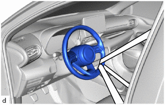
2. SECURE STEERING WHEEL
| (a) Secure the steering wheel with the seat belt in order to prevent rotation. HINT: This operation is useful to prevent damage to the spiral cable. |
|
3. REMOVE COLUMN HOLE COVER SILENCER SHEET
Click here

4. DISCONNECT NO. 2 STEERING INTERMEDIATE SHAFT ASSEMBLY
Click here

5. REMOVE FRONT WHEELS
Click here

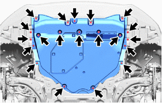
6. REMOVE NO. 1 ENGINE UNDER COVER ASSEMBLY
| (a) Remove the 4 bolts, 4 screws, 12 clips and center engine under cover from the vehicle body. |
|
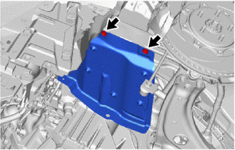
7. REMOVE ENGINE UNDER COVER LH
| (a) Remove the 2 clips and engine under cover LH from the vehicle body. |
|
8. REMOVE ENGINE UNDER COVER RH
HINT:
Perform the same procedure as for the LH side.
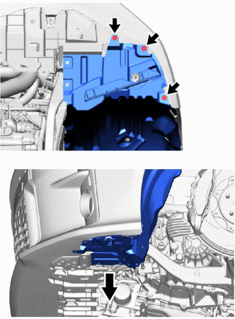
9. SEPARATE FRONT FENDER LINER LH
| (a) Remove the 3 screws and separate the front fender liner LH. |
|
10. SEPARATE FRONT FENDER LINER RH
HINT:
Perform the same procedure as for the LH side.
11. REMOVE CENTER NO. 4 ENGINE UNDER COVER
| (a) Remove the 4 bolts and center No. 4 engine under cover from the vehicle body. |
|
12. SEPARATE FRONT STABILIZER LINK ASSEMBLY LH
| (a) Remove the nut and separate the front stabilizer link assembly LH from the front stabilizer bar. NOTICE: Do not damage the boot of the ball joint. HINT: If the ball joint turns together with the nut, use a 6 mm hexagon socket wrench to hold the stud bolt. |
|
13. SEPARATE FRONT STABILIZER LINK ASSEMBLY RH
HINT:
Perform the same procedure as for the LH side.
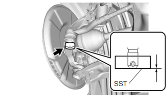
14. SEPARATE TIE ROD END SUB-ASSEMBLY LH
(a) Disengage the claw to remove the steering knuckle seal as shown in the illustration.
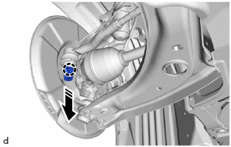
 | Remove in this Direction |
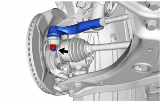
| (b) Remove the cotter pin and nut. |
|
| (c) Install SST to the tie rod end sub-assembly LH. SST: 09960-20010 09961-02060 NOTICE: Make sure that the lower ends of the tie rod end sub-assembly LH and SST are aligned. |
|
(d) Secure SST using a string.
NOTICE:
Be sure to tighten the string firmly to secure SST to the steering knuckle LH to prevent SST from falling off.
(e) Using SST, separate the tie rod end sub-assembly LH from the steering knuckle LH.
SST: 09960-20010
09961-02010
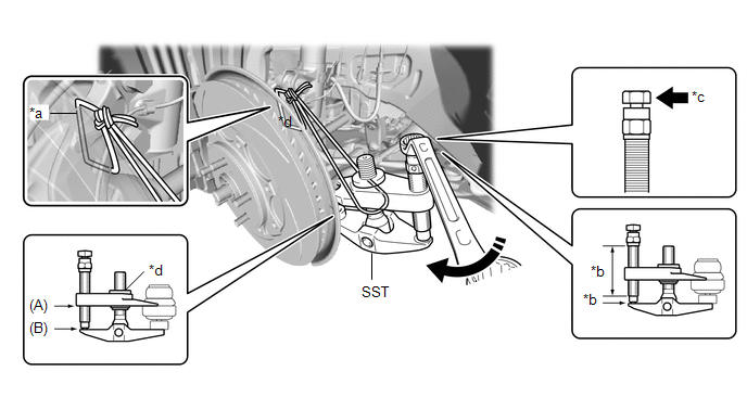
| *a | String | *b | Molybdenum Grease Application Area |
| *c | Place wrench here | *d | Center Nut |
 | Turn | - | - |
CAUTION:
Apply molybdenum grease to the bolt threads and the tip of SST.
NOTICE:
- Be sure to tighten the string firmly to secure SST to the steering knuckle LH to prevent SST from falling off.
- Install SST with the center nut so that (A) and (B) shown in the illustration are parallel. Otherwise, the ball joint dust cover may be damaged.
- Be sure to place the wrench on the part shown in the illustration.
- Do not damage the front disc brake dust cover.
- Do not damage the ball joint dust cover.
- Do not damage the steering knuckle LH.
15. SEPARATE TIE ROD END SUB-ASSEMBLY RH
HINT:
Perform the same procedure as for the LH side.
16. SEPARATE FRONT LOWER NO. 1 SUSPENSION ARM SUB-ASSEMBLY LH
Click here

17. SEPARATE FRONT LOWER NO. 1 SUSPENSION ARM SUB-ASSEMBLY RH
HINT:
Perform the same procedure as for the LH side.
18. REMOVE EXHAUST SENSOR CLAMP BRACKET
| (a) Disengage the 2 clamps. |
|
(b) Remove the bolt, and separate the exhaust sensor clamp bracket from the front suspension crossmember sub-assembly.
19. REMOVE FRONT SUSPENSION MEMBER REINFORCEMENT LH
| (a) Remove the 2 bolts and front suspension member reinforcement LH from the front suspension crossmember sub-assembly and vehicle body. |
|
20. REMOVE FRONT SUSPENSION MEMBER REINFORCEMENT RH
HINT:
Perform the same procedure as for the LH side.
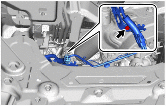
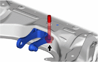
21. REMOVE FRONT SUSPENSION CROSSMEMBER SUB-ASSEMBLY
| (a) Remove the bolt and separate the wiring harness clamp bracket from the front suspension crossmember sub-assembly. |
|
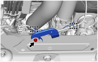
(b) Using a transmission jack and a wooden block, support the engine assembly with transaxle.
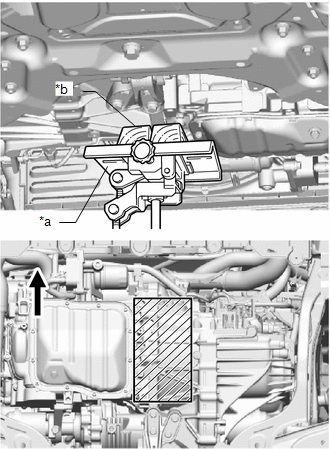
| *a | Transmission Jack |
| *b | Wooden Block |
 | Front of the Vehicle |
 | Wooden block placement location |
CAUTION:
- Support the engine assembly with transaxle until the front suspension crossmember sub-assembly is installed.
- If the support is removed before the front suspension crossmember sub-assembly is installed, the engine assembly with transaxle may drop.
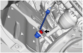
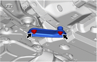
| (c) Remove the bolt and separate the engine moving control rod. |
|
(d) Support the front suspension crossmember sub-assembly with an engine lifter using 4 attachments or equivalent tools as shown in the illustration.
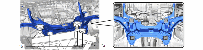
| *a | Engine Lifter | *b | Attachment |
 | Attachment placement location | - | - |
CAUTION:
-
The front suspension crossmember sub-assembly is a very heavy component. Make sure that it is supported securely.
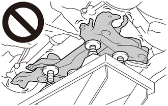
- If the front suspension crossmember sub-assembly is not securely supported, it may drop, resulting in serious injury.
NOTICE:
Use attachments to keep the front suspension crossmember sub-assembly level.
| (e) Remove the 2 bolts. |
|
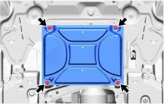
| (f) Remove the 4 bolts and front suspension crossmember sub-assembly. |
|
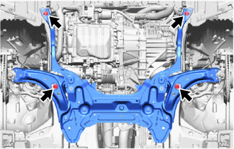
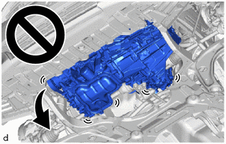
(g) Slowly lower the front suspension crossmember sub-assembly.
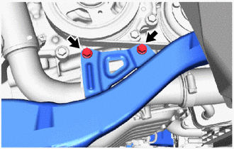
NOTICE:
- When lowering the front suspension crossmember sub-assembly, be careful not to damage the vehicle body or other components installed to the vehicle.
- Make sure that the front suspension crossmember sub-assembly not hit the protrusion of the reinforcement.
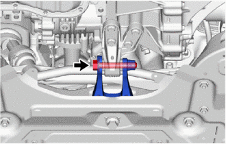
22. REMOVE ENGINE MOVING CONTROL ROD
| (a) Remove the bolt and engine moving control rod from the front suspension crossmember sub-assembly. |
|
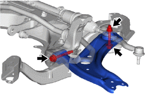
23. REMOVE FRONT LOWER NO. 1 SUSPENSION ARM SUB-ASSEMBLY LH
| (a) Remove the 2 bolts, nut and front lower No. 1 suspension arm sub-assembly LH from the front suspension crossmember sub-assembly. NOTICE: Loosen the bolt with the nut secured. |
|
24. REMOVE FRONT LOWER NO. 1 SUSPENSION ARM SUB-ASSEMBLY RH
HINT:
Perform the same procedure as for the LH side.
25. REMOVE STEERING LINK ASSEMBLY
Click here

26. REMOVE FRONT STABILIZER BAR
Click here

 Components
COMPONENTS ILLUSTRATION
*1 NO. 1 ENGINE UNDER COVER ASSEMBLY *2 CENTER NO. 4 ENGINE UNDER COVER *3 ENGINE UNDER COVER LH *4 ENGINE UNDER COVER RH
N*m (kgf*cm, ft...
 Installation
INSTALLATION PROCEDURE 1. INSTALL FRONT STABILIZER BAR Click here
2. INSTALL STEERING LINK ASSEMBLY Click here
3. TEMPORARILY INSTALL FRONT LOWER NO...
Other information:
Toyota Yaris XP210 (2020-2026) Reapir and Service Manual: Steering Angle Sensor Communication Stop Mode
DESCRIPTION Detection Item Symptom Trouble Area Steering Angle Sensor Communication Stop Mode Communication stop for "Spiral cable (Steering Angle Sensor)" is indicated on the "Communication Bus Check" screen of the GTS. Click here Steering sensor branch line or connector Power source circuit of steering sensor Steering sensor ground circuit Steering sensor WIRING DIAGRAM CAUTION / NOTICE / HINT CAUTION: When performing the confirmation driving pattern, obey all speed limits and traffic laws...
Toyota Yaris XP210 (2020-2026) Reapir and Service Manual: Components
COMPONENTS ILLUSTRATION *1 REAR SHOCK ABSORBER ASSEMBLY *2 REAR STABILIZER LINK ASSEMBLY *3 REAR UPPER CONTROL ARM ASSEMBLY *4 REAR STABILIZER BAR *5 CAP - - Tightening torque for "Major areas involving basic vehicle performance such as moving/turning/stopping" : N*m (kgf*cm, ft...
Categories
- Manuals Home
- Toyota Yaris Owners Manual
- Toyota Yaris Service Manual
- Opening and Closing the Liftgate/Trunk Lid
- Fuel Gauge
- Maintenance
- New on site
- Most important about car
Break-In Period
No special break-in is necessary, but a few precautions in the first 600 miles (1,000 km) may add to the performance, economy, and life of the vehicle.
Do not race the engine. Do not maintain one constant speed, either slow or fast, for a long period of time. Do not drive constantly at full-throttle or high engine rpm for extended periods of time. Avoid unnecessary hard stops. Avoid full-throttle starts.