Toyota Yaris: Front Suspension Member / Installation
INSTALLATION
PROCEDURE
1. INSTALL FRONT STABILIZER BAR
Click here

2. INSTALL STEERING LINK ASSEMBLY
Click here

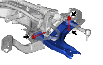
3. TEMPORARILY INSTALL FRONT LOWER NO. 1 SUSPENSION ARM SUB-ASSEMBLY LH
| (a) Temporarily install the front lower No. 1 suspension arm sub-assembly LH to the front suspension crossmember sub-assembly with the 2 bolts and nut. |
|
4. TEMPORARILY INSTALL FRONT LOWER NO. 1 SUSPENSION ARM SUB-ASSEMBLY RH
HINT:
Perform the same procedure as for the LH side.
5. INSTALL ENGINE MOVING CONTROL ROD
(a) Install the engine moving control rod to the front suspension crossmember sub-assembly with the bolt.
Torque:
200 N·m {2039 kgf·cm, 148 ft·lbf}
6. INSTALL FRONT SUSPENSION CROSSMEMBER SUB-ASSEMBLY
(a) Slowly jack up the front suspension crossmember sub-assembly with an engine lifter using 4 attachments or equivalent tools.
CAUTION:
- The front suspension crossmember sub-assembly is a very heavy component. Make sure that it is supported securely.
- If the front suspension crossmember sub-assembly is not securely supported, it may drop, resulting in serious injury.
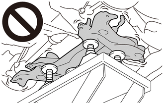
NOTICE:
- Use attachments to keep the front suspension crossmember sub-assembly level.
- Make sure that the front suspension crossmember sub-assembly not hit the protrusion of the reinforcement.
-
After installation, check that the claws of the steering column hole cover base are not disengaged.
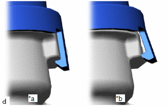
*a
OK
*b
NG
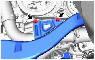
| (b) Install the front suspension crossmember sub-assembly to the vehicle body with the 4 bolts. Torque: 95 N·m {969 kgf·cm, 70 ft·lbf} |
|
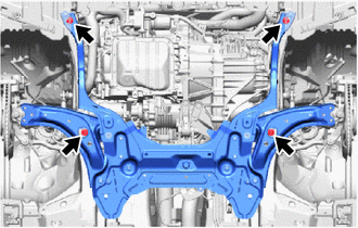
| (c) Install the 2 bolts. Torque: 7.0 N·m {71 kgf·cm, 62 in·lbf} |
|
(d) Lower the engine lifter.
(e) Install the engine moving control rod with the bolt.
Torque:
170 N·m {1734 kgf·cm, 125 ft·lbf}
(f) Install the wiring harness clamp bracket to the front suspension crossmember sub-assembly with the bolt.
Torque:
13 N·m {133 kgf·cm, 10 ft·lbf}
7. INSTALL FRONT SUSPENSION MEMBER REINFORCEMENT LH
(a) Install the front suspension member reinforcement LH to the front suspension crossmember sub-assembly and vehicle body with the 2 bolts.
Torque:
95 N·m {969 kgf·cm, 70 ft·lbf}
8. INSTALL FRONT SUSPENSION MEMBER REINFORCEMENT RH
HINT:
Perform the same procedure as for the LH side.
9. INSTALL EXHAUST SENSOR CLAMP BRACKET
(a) Install the exhaust sensor clamp bracket to the front suspension crossmember sub-assembly with the bolt.
Torque:
13 N·m {133 kgf·cm, 10 ft·lbf}
(b) Engage the 2 clamps.
10. CONNECT FRONT LOWER NO. 1 SUSPENSION ARM SUB-ASSEMBLY LH
Click here

11. CONNECT FRONT LOWER NO. 1 SUSPENSION ARM SUB-ASSEMBLY RH
HINT:
Perform the same procedure as for the LH side.
12. CONNECT TIE ROD END SUB-ASSEMBLY LH
| (a) Connect the tie rod end sub-assembly LH to the steering knuckle LH with the nut. Torque: 49 N·m {500 kgf·cm, 36 ft·lbf} NOTICE:
|
|
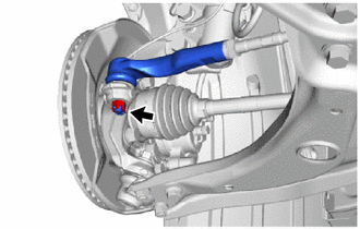
(b) Install a new cotter pin.
(c) Engage the claw to install the steering knuckle seal as shown in the illustration.
HINT:
Check that the steering knuckle seal is securely installed.
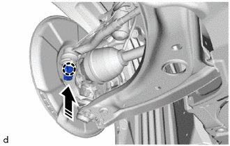
 | Install in this Direction |
13. CONNECT TIE ROD END SUB-ASSEMBLY RH
HINT:
Perform the same procedure as for the LH side.
14. CONNECT FRONT STABILIZER LINK ASSEMBLY LH
(a) Connect the front stabilizer link assembly LH to the front stabilizer bar with the nut.
Torque:
74 N·m {755 kgf·cm, 55 ft·lbf}
NOTICE:
Do not damage the boot of the ball joint.
HINT:
If the ball joint turns together with the nut, use a 6 mm hexagon socket wrench to hold the stud bolt.
15. CONNECT FRONT STABILIZER LINK ASSEMBLY RH
HINT:
Perform the same procedure as for the LH side.
16. INSTALL FRONT FENDER LINER LH
(a) Install the front fender liner LH to the vehicle body with the 3 screws.
17. INSTALL FRONT FENDER LINER RH
HINT:
Perform the same procedure as for the LH side.
18. INSTALL FRONT WHEELS
Click here

19. CONNECT NO.2 STEERING INTERMEDIATE SHAFT ASSEMBLY
Click here

20. INSTALL COLUMN HOLE COVER SILENCER SHEET
Click here

21. STABILIZE SUSPENSION
Click here

22. FULLY TIGHTEN FRONT LOWER NO. 1 SUSPENSION ARM SUB-ASSEMBLY LH
Click here

23. FULLY TIGHTEN FRONT LOWER NO. 1 SUSPENSION ARM SUB-ASSEMBLY RH
HINT:
Perform the same procedure as for the LH side.
24. INSTALL CENTER NO. 4 ENGINE UNDER COVER
(a) Install the center No. 4 engine under cover to the vehicle body with the 4 bolts.
Torque:
5.0 N·m {51 kgf·cm, 44 in·lbf}
25. INSTALL ENGINE UNDER COVER LH
(a) Install the engine under cover LH to the vehicle body with the 2 clips.
26. INSTALL ENGINE UNDER COVER RH
HINT:
Perform the same procedure as for the LH side.
27. INSTALL NO. 1 ENGINE UNDER COVER ASSEMBLY
(a) Install the No. 1 engine under cover assembly to the vehicle body with the 4 bolts, 4 screws and 12 clips.
Torque:
Bolt :
5.0 N·m {51 kgf·cm, 44 in·lbf}
28. INSPECT AND ADJUST FRONT WHEEL ALIGNMENT
Click here

 Removal
REMOVAL CAUTION / NOTICE / HINT The necessary procedures (adjustment, calibration, initialization, or registration) that must be performed after parts are removed, installed, or replaced during the front suspension crossmember sub-assembly removal/installation are shown below...

Other information:
Toyota Yaris XP210 (2020-2026) Reapir and Service Manual: Terminals Of Ecu
TERMINALS OF ECU NOTICE: After the ignition switch is turned off, there may be a waiting time before disconnecting the negative (-) auxiliary battery terminal. Click here When disconnecting and reconnecting the auxiliary battery. Click here CHECK POWER DISTRIBUTION BOX ASSEMBLY AND MAIN BODY ECU (MULTIPLEX NETWORK BODY ECU) (a) Remove the main body ECU (multiplex network body ECU) from the power distribution box assembly...
Toyota Yaris XP210 (2020-2026) Reapir and Service Manual: Removal
REMOVAL PROCEDURE 1. REMOVE MULTIPLEX NETWORK MASTER SWITCH ASSEMBLY WITH FRONT ARMREST BASE UPPER PANEL Click here 2. REMOVE OUTER MIRROR SWITCH ASSEMBLY (a) Using a screwdriver with its tip wrapped in protective tape, disengage the claws to remove the outer mirror switch assembly...
Categories
- Manuals Home
- Toyota Yaris Owners Manual
- Toyota Yaris Service Manual
- Diagnostic Trouble Code Chart
- Battery Monitor Module General Electrical Failure (P058A01)
- G16e-gts (engine Mechanical)
- New on site
- Most important about car
Supplemental Restraint System (SRS) Precautions
The front and side supplemental restraint systems (SRS) include different types of air bags. Please verify the different types of air bags which are equipped on your vehicle by locating the “SRS AIRBAG” location indicators. These indicators are visible in the area where the air bags are installed.
The air bags are installed in the following locations:
The steering wheel hub (driver air bag) The front passenger dashboard (front passenger air bag) The outboard sides of the front seatbacks (side air bags) The front and rear window pillars, and the roof edge along both sides (curtain air bags)