Toyota Yaris: Front Brake / Reassembly
REASSEMBLY
PROCEDURE
1. TEMPORARILY TIGHTEN FRONT DISC BRAKE BLEEDER PLUG
(a) Temporarily tighten the front disc brake bleeder plug to the front disc brake cylinder.
HINT:
Fully tighten the front disc brake bleeder plug after bleeding the system.
2. INSTALL FRONT DISC BRAKE BLEEDER PLUG CAP
(a) Install the front disc brake bleeder plug cap to the front disc brake bleeder plug.
3. INSTALL PISTON SEAL
(a) Apply lithium soap base glycol grease to the entire circumference of 4 new piston seals.
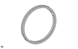
 | Lithium Soap Base Glycol Grease |
| (b) Install the 4 piston seals to the front disc brake cylinder. NOTICE:
|
|
4. INSTALL CYLINDER BOOT
(a) Apply a light layer of lithium soap base glycol grease to the inner surfaces of 4 new cylinder boots.
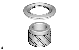
 | Lithium Soap Base Glycol Grease |
(b) Apply a light layer of lithium soap base glycol grease to the contact surfaces of the 4 front disc brake pistons.
| (c) Install the 4 cylinder boots to the 4 front disc brake pistons. NOTICE: Securely install the cylinder boot into the groove of the front disc brake piston. |
|
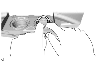
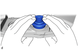
5. INSTALL FRONT DISC BRAKE PISTON
| (a) Install the 4 front disc brake pistons to the front disc brake cylinder. NOTICE: Do not forcibly install the front disc brake piston into the front disc brake cylinder. |
|
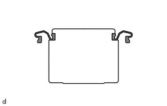
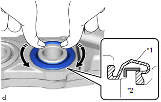
| (b) Push in the 4 cylinder boots and engage the 4 cylinder boots to each retainer of the front disc brake cylinder. NOTICE:
|
|
 Inspection
INSPECTION PROCEDURE 1. INSPECT BRAKE CYLINDER AND PISTON (a) Check the front disc brake cylinder bore and front disc brake piston for rust and scoring...
 Installation
INSTALLATION CAUTION / NOTICE / HINT HINT:
Use the same procedure for the RH side and LH side.
The following procedure is for the LH side.
PROCEDURE 1...
Other information:
Toyota Yaris XP210 (2020-2026) Reapir and Service Manual: Disassembly
DISASSEMBLY CAUTION / NOTICE / HINT CAUTION: Wear protective gloves. Sharp areas on the parts may injure your hands. PROCEDURE 1. REMOVE REAR SEAT HEADREST ASSEMBLY (a) Remove the rear seat headrest assembly. 2. REMOVE REAR SEATBACK LOCK UPPER BEZEL (a) Disengage the claws to remove the rear seatback lock upper bezel...
Toyota Yaris XP210 (2020-2026) Reapir and Service Manual: Front Camera Module Communication Stop Mode
DESCRIPTION Detection Item Symptom Trouble Area Front Camera Module Communication Stop Mode Communication stop for "Front Camera Module" is indicated on the "Communication Bus Check" screen of the GTS. Click here Forward recognition camera branch line or connector Power source circuit of forward recognition camera Forward recognition camera ground circuit Forward recognition camera WIRING DIAGRAM CAUTION / NOTICE / HINT CAUTION: When performing the confirmation driving pattern, obey all speed limits and traffic laws...
Categories
- Manuals Home
- Toyota Yaris Owners Manual
- Toyota Yaris Service Manual
- To Set Speed
- Diagnostic Trouble Code Chart
- Brake System Control Module "A" System Voltage System Voltage Low (C137BA2)
- New on site
- Most important about car
Refueling
Before refueling, close all the doors, windows, and the liftgate/trunk lid, and switch the ignition OFF.
To open the fuel-filler lid, pull the remote fuel-filler lid release.
